
A method for repairing blade edge with high energy beam

A technology of high-energy beam and blade edge, which is applied in the direction of metal material coating process, coating, etc., can solve the problems of repaired blade collapse, low deposition precision, deep heat-affected zone, etc., and achieve the effect of solving the collapse of the substrate

Active Publication Date: 2022-04-12
AVIC BEIJING AERONAUTICAL MFG TECH RES INST
View PDF6 Cites 0 Cited by
  • Summary
  • Abstract
  • Description
  • Claims
  • Application Information

AI Technical Summary

Problems solved by technology

[0006] The present invention aims to solve the problems existing in the prior art that during material deposition, forming or repair, large melt pool spots, low deposition accuracy, low scanning speed and deep heat-affected zone will cause collapse, deformation and decline in mechanical properties of the repaired blade. technical problem

Method used


Image

  • A method for repairing blade edge with high energy beam
  • A method for repairing blade edge with high energy beam
  • A method for repairing blade edge with high energy beam

Examples


Embodiment Construction

[0035] The specific implementation manners of the present invention will be further described in detail below in conjunction with the accompanying drawings and embodiments. The following examples are used to illustrate the present invention, but are not intended to limit the scope of the present invention.

[0036] In the description of the present invention, it should be understood that the terms "center", "longitudinal", "transverse", "upper", "lower", "front", "rear", "left", "right", "vertical The orientations or positional relationships indicated by "straight", "horizontal", "top", "bottom", "inner", "outer", etc. are based on the orientation or positional relationship shown in the drawings, and are only for the convenience of describing the present invention and simplifying the description , rather than indicating or implying that the device or element referred to must have a particular orientation, be constructed and operate in a particular orientation, and thus should ...


PUM

PropertyMeasurementUnit
thicknessaaaaaaaaaa

Abstract

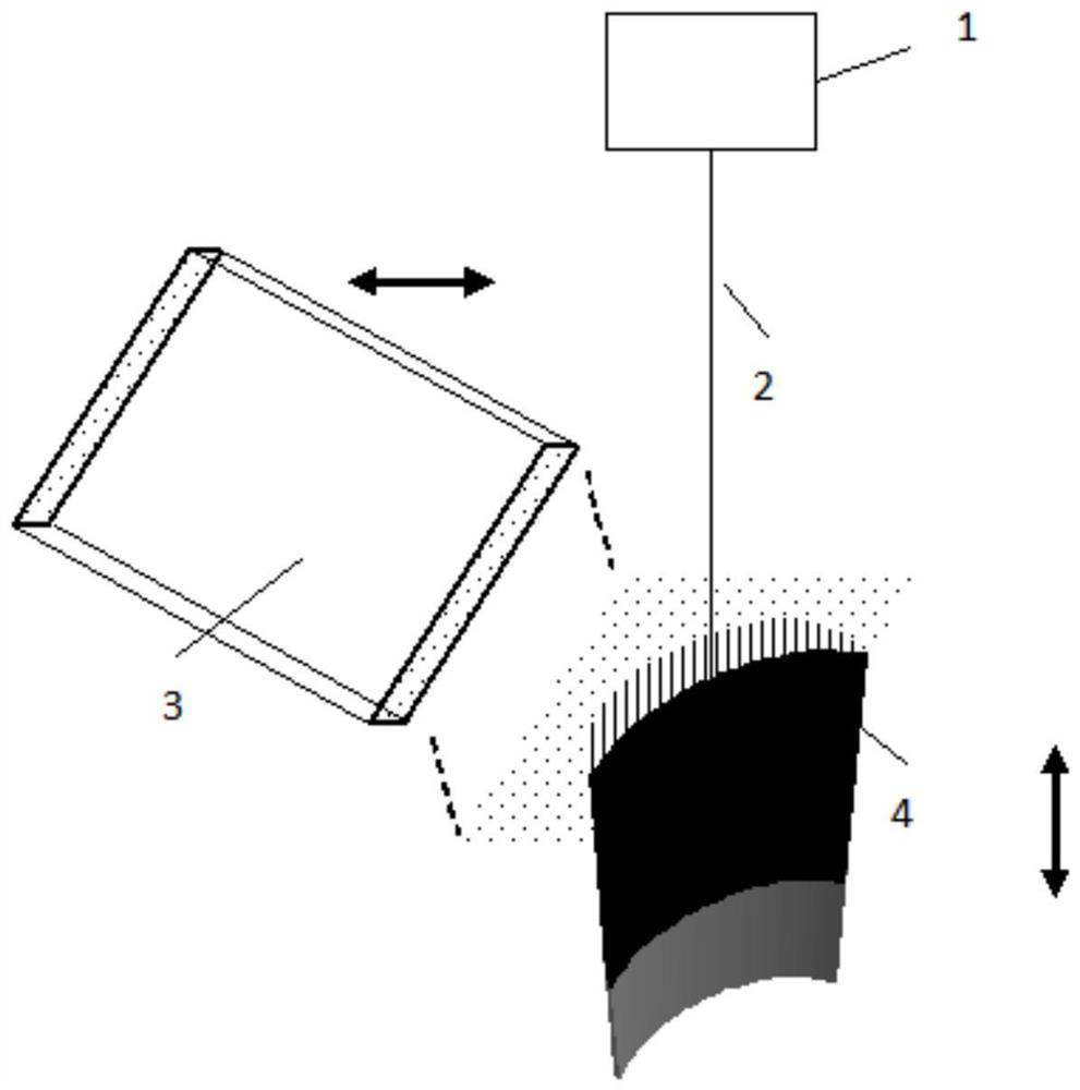
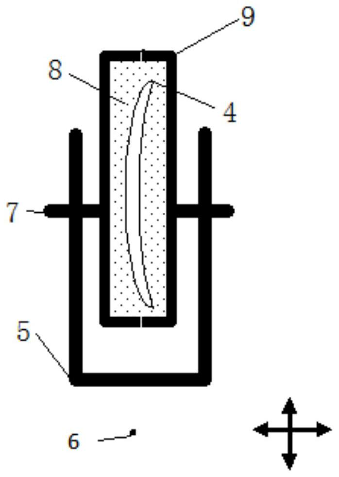
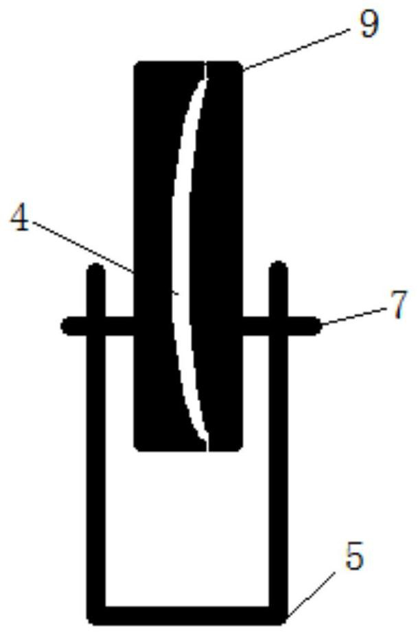
The invention discloses a method for repairing the edge of a blade with a high-energy beam. The steps include: measuring the damage size of the damage area, obtaining the damage size in the chord direction and the radial direction, and cutting the damage area in a plane with the damage size as the cutting position; Based on the original digital model of the blade, the digital model of the blank in the damaged area is intercepted based on the damage size; the digital model of the blank in the damaged area is used as input and the slice trajectory generation software is used to form the planning model of the scanning path of the damaged area; the blade is placed on the fixed tooling, Keep the surface of the damaged area level and thicken the damaged area; place the galvanometer above the blade and keep it horizontal so that the focus of the high-energy beam is on the surface of the damaged area; fix the powder feeding tube above the surface of the damaged area; place the blade on an inert In the gas protection box, when the oxygen content is lower than 1000PPM, turn on the airborne powder feeder and the high-energy beam emitter, and start scanning deposition according to the scanning path planning model; after the scanning is completed and the blade is cooled to room temperature, the blade is taken out.

Description

technical field [0001] The invention relates to the field of high-energy beam repair, in particular to a method for repairing blade edges with high-energy beam. Background technique [0002] The existing blades of the high-pressure compressor of the engine adopt the method of disc separation, and the damaged blades are repaired by replacing them separately. The repair schemes currently used for the blisk of high-pressure compressors include high-energy beam (laser, electron beam and plasma beam) fusion welding, high-energy beam additive and linear friction welding. However, laser cladding for repairing the edge can only be used for thicker blades. There is no effective way to repair the edge of the blade below 1mm. It must be thickened to ensure that the edge substrate does not collapse. Shape restoration is achieved by deposition or welding. [0003] At present, in the high-energy beam deposition technology such as laser, the minimum size of the molten pool is 1mm, which ...

Claims


Application Information

Patent Timeline
Patent Type & Authority Patents(China)
IPC IPC(8): C23C24/10
CPCC23C24/103
Inventor 刘琦单飞虎王玉岱李怀学胡全栋
Owner AVIC BEIJING AERONAUTICAL MFG TECH RES INST
Learn More