
Multi-cavity steel plate build-in steel tube high-strength concrete shear wall

A high-strength concrete and shear wall technology, applied in the direction of walls, buildings, building components, etc., can solve the problems of reduced building use area, large shear wall thickness, poor shear deformation ability, etc., to prevent out-of-plane instability , the structure is simple, the effect of improving the deformation ability

Pending Publication Date: 2020-05-08
GUANGZHOU UNIVERSITY
View PDF0 Cites 5 Cited by
  • Summary
  • Abstract
  • Description
  • Claims
  • Application Information

AI Technical Summary

Problems solved by technology

Traditional ordinary reinforced concrete has poor shear deformation capacity, low ductility, easy cracking, and high brittleness. Under high axial pressure, a large shear wall thickness is required. Too thick walls increase the weight of the structure, which is not conducive to Anti-seismic, while reducing the building area and increasing the basic cost

Method used


Image

  • Multi-cavity steel plate build-in steel tube high-strength concrete shear wall
  • Multi-cavity steel plate build-in steel tube high-strength concrete shear wall
  • Multi-cavity steel plate build-in steel tube high-strength concrete shear wall

Examples


Embodiment 1

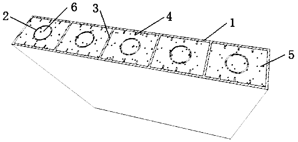
[0031] Such as Figure 1-Figure 3 The shown multi-cavity steel pipe high-strength concrete shear wall contains steel pipes, including outsourcing steel plates 1, partition plates 3 and steel pipes 2; multiple outsourcing steel plates 1 are connected to form a closed space with a cross section. Partition plates 3 are provided at intervals to divide the space into several cavities, and the steel pipes 2 are respectively arranged in each cavity, and concrete is poured into the cavities and the steel pipes 2 . Wherein, the steel pipe 2 is a hollow circular steel pipe, and the outsourcing steel plates 1 are connected by welding to form a space with a closed cross section (that is, closed around). Ordinary concrete 5 is filled inside the outer steel formwork, and the steel plate and concrete are mutually restrained and work together. Filling ordinary concrete 5 inside the outer steel plate 1 can restrain the outer steel plate 1, and can effectively restrain the buckling of the steel...

Embodiment 2

[0040] This embodiment is the same as embodiment 1 except the following technical features:

[0041] The partition boards 3 are arranged at intervals along the width direction of the shear wall, and the two ends of each partition board 3 are respectively connected with two oppositely arranged outer cladding steel plates 1, so as to divide the space into several cavities body, at least one steel pipe 2 is arranged in the cavity. Under the condition of satisfying the use requirements, the partition plate 3 can be arranged along the length direction or the width direction of the shear wall. When the partition plate 3 is arranged along the width direction of the shear wall, the steel pipe 2 can be arranged in the vertical direction, at this time, the steel pipe 2 is at the same height as the shear wall, or the steel pipe 2 can be arranged in the horizontal direction, at this time, the steel pipe 2 and the shear force The wall is equal in length.


PUM


Abstract

The invention relates to the technical field of construction engineering, and discloses a multi-cavity steel plate build-in steel tube high-strength concrete shear wall. The shear wall comprises outerwrapping steel plates, partition plates and steel tubes. The multiple outer wrapping steel plates are connected to form a space with the closed cross section, and the partition plates are arranged inside the space at intervals, so that the space is partitioned into a plurality of cavity bodies. The steel tubes are arranged in the cavity bodies respectively. Concrete is poured into the cavity bodies and the steel tubes. The shear wall has the beneficial effects that the restraint effect of the steel plates and the steel tubes for concrete is sufficiently utilized, the bearing capacity, rigidity and ductility of the shear wall are enhanced, the good anti-seismic performance is achieved, the outer side steel plates can also be used as formworks, construction is easy and convenient, the construction period is shortened, and the shear wall is expected to be a novel shear wall system in a super high-rise building.

Description

technical field [0001] The invention relates to the technical field of construction engineering, in particular to a high-strength concrete shear wall with steel pipes embedded in multi-cavity steel plates. Background technique [0002] In recent years, high-rise buildings have emerged one after another, and their height and complexity have been constantly updated. With the improvement of building function requirements and the increase of building height, the performance requirements of shear walls are getting higher and higher. Traditional ordinary reinforced concrete has poor shear deformation capacity, low ductility, easy cracking, and high brittleness. Under high axial pressure, a large shear wall thickness is required. Too thick walls increase the weight of the structure, which is not conducive to Anti-seismic, while reducing the building area and increasing the basic cost. Shear walls and core tubes composed of shear walls are the core part of high-rise building anti-s...

Claims


Application Information

Patent Timeline
Patent Type & Authority Applications(China)
IPC IPC(8): E04B2/56
CPCE04B2/56
Inventor 马玉宏邱洁鹏赵桂峰陈嘉佳吴小平赵子龙
Owner GUANGZHOU UNIVERSITY
Learn More