Heat-collecting column and window constituting form and usage method of the heat-collecting column

A technology of collecting columns and windows, which is applied to solar collectors using working fluid, thermal insulation of solar collectors, and solar collectors in specific environments, etc. Problems such as low integration of solar renewable resource building design and poor heat collection effect

Active Publication Date: 2021-08-31
CHINA ARCHITECTURE DESIGN & RES GRP CO LTD
View PDF6 Cites 0 Cited by
  • Summary
  • Abstract
  • Description
  • Claims
  • Application Information

AI Technical Summary

Problems solved by technology

[0004] Therefore, the present invention aims to provide a heat-collecting column constituting a window, a window and a method for using the heat-collecting column, so as to solve the problem that energy-saving windows in the prior art do not fully utilize solar energy and have poor heat-collecting effects. It is impossible to achieve clean heating, house insulation and ventilation, and the integration of solar renewable resources and architectural design is not high

Method used


Image

  • Heat-collecting column and window constituting form and usage method of the heat-collecting column
  • Heat-collecting column and window constituting form and usage method of the heat-collecting column
  • Heat-collecting column and window constituting form and usage method of the heat-collecting column

Examples


Embodiment 1

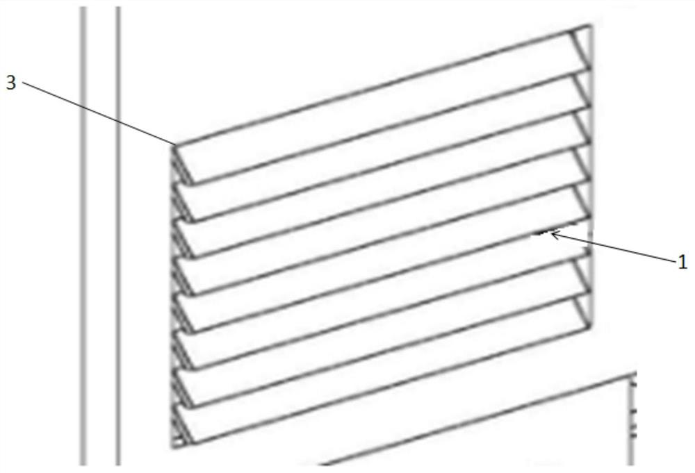
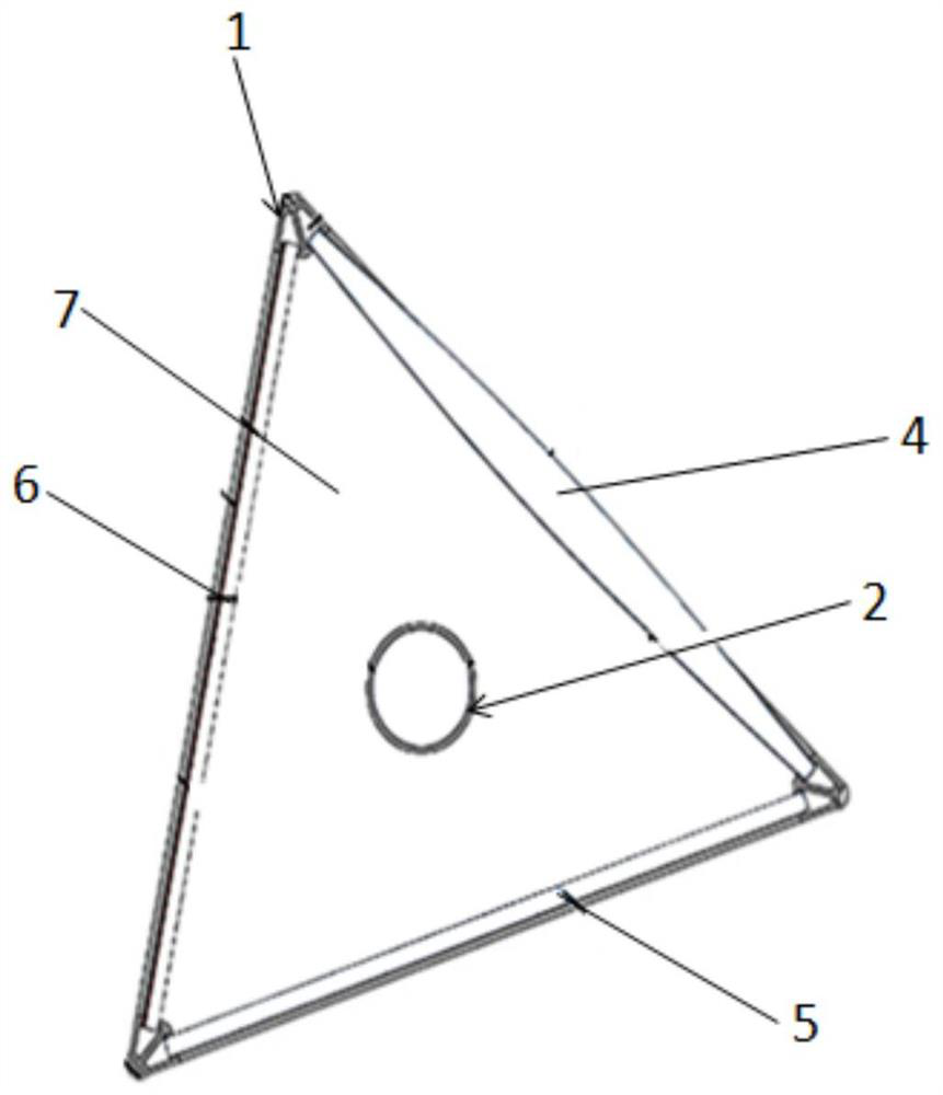
[0046] A kind of heat-collecting column and form and the usage method of this heat-collecting column that this embodiment provides, as figure 1 and figure 2 As shown, a heat-collecting column forming a form includes: a window frame 3 and a plurality of heat-collecting columns 1 arranged on the window frame 3 through a rotating device, and two ends of the heat-collecting column 1 are provided with rotating brackets. The rotating bracket installs the heat-collecting column 1 on the window frame 3, so that the heat-collecting column 1 and the window are fused together. 1 is a column with a triangular cross-section, and the three sides can achieve different functions. By setting the heat collecting part 2 inside the heat collecting column 1, the heat collecting part 2 has good heat preservation and heat collecting performance, so as to reduce Heat loss when transferring heat energy to the room, the tail of the heat collecting part 2 can also be equipped with a heat insulation s...

Embodiment 2

[0056] The difference between this embodiment and Embodiment 1 is that the heat storage medium of the heat collection component 2 is different, and the heat storage medium in the heat collection component 2 can be set as a vacuum gas, and the heat collection component 2 is provided with a heat transfer tube and an indoor ground. The floor heating pipeline on the ground is connected, and the heat transfer pipe in the heat collecting part 2 is heated by the collected solar energy to transfer heat energy to the floor heating pipeline on the indoor ground to heat the house.

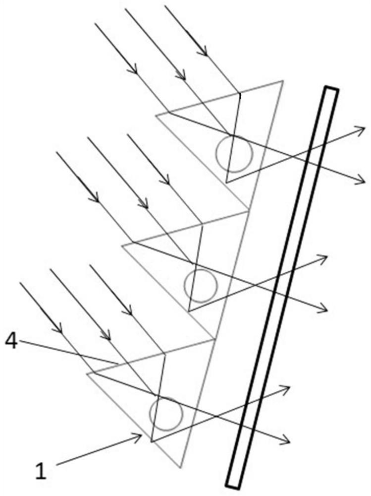
[0057] Of course, the present invention does not specifically limit the shape of the heat-collecting column 1. In other embodiments, the heat-collecting column 1 can also be a cylinder with a square cross section; the four sides of the heat-collecting column 1 are convex lens structures 4, diffuse A reflective material layer 5, and two light-blocking material layers 6.

[0058] Of course, the present inventio...


PUM


Abstract

The invention discloses a heat-collecting column constituting a window, a window and a method for using the heat-collecting column. The heat-collecting column constituting the window includes: a heat-collecting column, and the heat-collecting column is a cylinder with a polygonal cross section , the inside of the heat-collecting column is provided with a heat-collecting component for collecting heat, and the heat-collecting component is connected to the heat-collecting terminal; The energy-saving windows in the technology do not fully utilize solar energy, and cannot achieve clean heating, house insulation, and ventilation, and the integration of solar energy renewable resources and architectural design is not high.

Description

technical field [0001] The invention relates to the field of energy saving and environmental protection, in particular to a heat collecting column constituting a window, a window and a method for using the heat collecting column. Background technique [0002] Solar energy is known as clean energy and safe energy. Not only is it non-polluting, it is cleaner than conventional energy sources, and it is also harmless. The state's continuous introduction of encouraging policies for the use of solar clean energy has improved people's understanding and recognition of solar products and increased their desire for demand for solar products. [0003] Chinese patent document CN201991402U discloses a fixed solar photothermal aluminum alloy energy-saving window, such as Figure 7 As shown, the fixed solar photothermal aluminum alloy energy-saving window includes a solar heat collecting plate, a window, and a water storage tank, and is connected to the solar heat collecting plate through...

Claims


Application Information

Patent Timeline
Patent Type & Authority Patents(China)
IPC IPC(8): F24S20/63F24S23/30F24S60/30F24S80/60F24S10/40F24D15/00E06B7/28
CPCE06B7/28F24D15/00F24D2200/14F24S10/40F24S20/63F24S23/30F24S60/30F24S80/60Y02B10/20Y02E10/44
Inventor 贺靖杨慧琳李嘉慧薛晓宁黄菲
Owner CHINA ARCHITECTURE DESIGN & RES GRP CO LTD
Why Eureka
Try Eureka