Far-field laser spot measuring device

A laser spot and measuring device technology, applied in the field of laser detection, can solve the problems of inaccurate measurement results and lack of collected information, and achieve the effect of powerful logic function, high flexibility, and easy replacement.

Inactive Publication Date: 2020-05-08
NANJING UNIV OF SCI & TECH
View PDF7 Cites 7 Cited by
  • Summary
  • Abstract
  • Description
  • Claims
  • Application Information

AI Technical Summary

Problems solved by technology

This method can flexibly select the sampling position and efficiently process the sampled data, but when encountering a laser with a narrow pulse width, the collected information will be missing, and the measurement results are not very accurate

Method used


Image

  • Far-field laser spot measuring device
  • Far-field laser spot measuring device
  • Far-field laser spot measuring device

Examples


Embodiment Construction

[0017] In order to make the purpose, technical solution and advantages of the present application clearer, the present application will be further described in detail below in conjunction with the accompanying drawings and embodiments. It should be understood that the specific embodiments described here are only used to explain the present application, and are not intended to limit the present application.

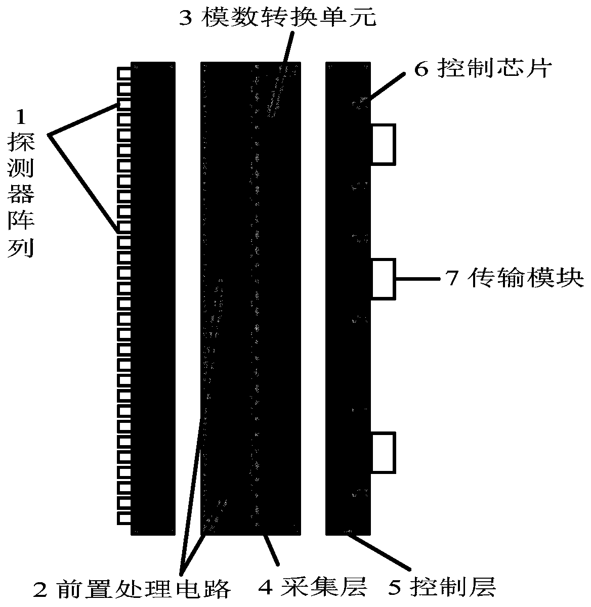
[0018] to combine figure 1 , the present invention proposes a far-field laser spot measurement device, including a detection layer, an acquisition layer and a control layer arranged in sequence;

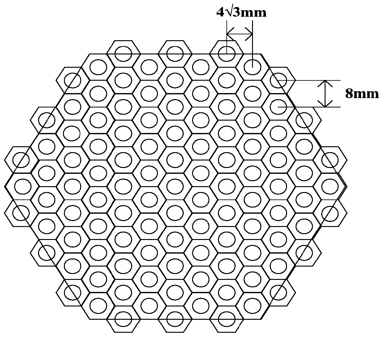
[0019] A detector array for detecting far-field laser light is arranged on the detection layer;

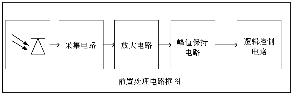
[0020] A plurality of pre-processing circuits corresponding to the detectors are set on the acquisition layer for converting the laser signals collected by the detector array into analog electrical signals, and a plurality of AD conversion units corresponding to the pre-processing c...


PUM


Abstract

The invention discloses a far-field laser spot measuring device. The far-field laser spot measuring device comprises a detection layer, an acquisition layer and a control layer which are sequentiallyarranged, wherein the detection layer is provided with a detector array which is used for detecting far-field laser and is arranged in a honeycomb structure; the acquisition layer is provided with a plurality of pre-processing circuits corresponding to the detectors and used for converting laser signals acquired by means of the detector array into analog electric signals, and the acquisition layeris further provided with a plurality of AD conversion units corresponding to the pre-processing circuits and used for converting the analog electric signals into digital electric signals; the controllayer is provided with a control chip and a peripheral circuit thereof, is used for controlling the acquisition time sequence of the AD conversion unit and storing the data acquired by the AD conversion unit, and is further provided with a transmission module which is used for transmitting the data stored in the control chip to an upper computer; and the upper computer is used for processing thedata to obtain the parameters of far-field laser spots. According to the far-field laser spot measuring device, the narrow pulse laser can be measured, the operation is simple, the result is precise,and the reliability is high.

Description

technical field [0001] The invention relates to the technical field of laser detection, in particular to a far-field laser spot measuring device. Background technique [0002] As a core driving force in the field of industrial manufacturing, laser technology continues to develop rapidly. The power of lasers is getting higher and higher, and the average power has exceeded 100,000 watts; the pulse speed of lasers is getting faster and faster, and ultrafast lasers have achieved rapid development. With simpler structures, more convenient operations, lower costs and More stable performance, out of the laboratory into industrial applications. Today, the application of laser technology has penetrated into all aspects of life, which makes the accurate measurement of the parameters of the laser itself, such as power and energy, extremely important. In addition, some laser pulse widths are relatively narrow, in order to reduce the loss of laser information, a high-speed signal proce...

Claims


Application Information

Patent Timeline
Patent Type & Authority Applications(China)
IPC IPC(8): G01J1/44
CPCG01J1/44G01J2001/444G01J2001/448
Inventor 富容国张红周鸣陈江南杜振伟段赐琛钱芸生刘磊张俊举张益军邱亚峰
Owner NANJING UNIV OF SCI & TECH
Why Eureka
Try Eureka