Projection lens

A projection lens and lens technology, applied in the field of projection lenses, can solve the problems of weakened long-distance imaging of telephoto lenses, poor high-definition image imaging effects of short-focus lenses, and have not been well resolved to achieve the effect of a large field of view

Pending Publication Date: 2020-05-08
北京乐都展陈科技发展有限公司
View PDF0 Cites 0 Cited by
  • Summary
  • Abstract
  • Description
  • Claims
  • Application Information

AI Technical Summary

Problems solved by technology

[0003] However, the current projector lens is greatly affected by changes in visible light, and the long-distance imaging weakening pro

Method used


Image

  • Projection lens
  • Projection lens
  • Projection lens

Examples


Embodiment Construction

[0047] In order to make the purpose, technical solution and advantages of the present invention clearer, the packaging bag of the present invention will be further described in detail below through examples and in conjunction with the accompanying drawings. It should be understood that the specific embodiments described here are only used to explain the present invention, not to limit the present invention.

[0048] It should be noted that when an element is referred to as being "fixed" to another element, it can be directly on the other element or an intervening element can also be present. When an element is said to be "connected" to another element, it can be directly connected to the other element or intervening elements may also be present. In contrast, when an element is referred to as being "directly on" another element, there are no intervening elements present. The terms "vertical," "horizontal," "left," "right," and similar expressions are used herein for purposes o...


PUM


Abstract

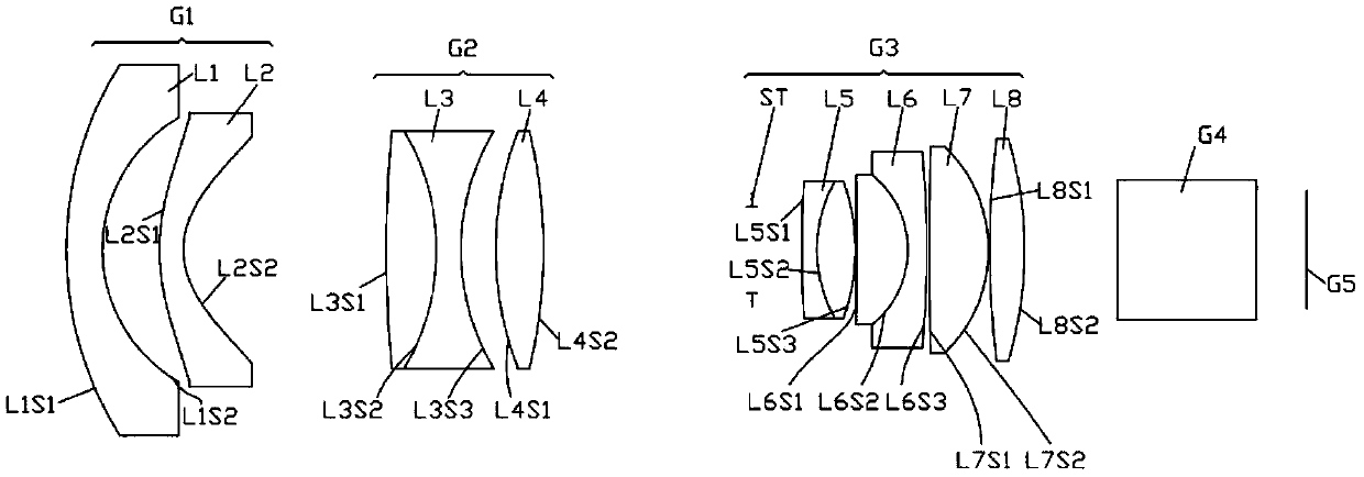
The invention relates to a projection lens, which sequentially comprises a first lens group, a second lens group, a third lens group and a prism from an object end to an imaging surface along the optical axis direction. The first lens group has negative focal power; the second lens group has positive focal power; the third lens group has positive focal power. According to the invention, a reversetelephoto structure is adopted, so that the lens has a large field of view and a long back focus. The first lens group adopts negative focal power and can effectively balance off-axis aberration, andthe aperture ST is arranged between the second lens group G2 and the third lens group G3, so that the whole lens structure is symmetrical relative to the aperture ST, and coma aberration, astigmatism,vertical axis chromatic aberration, distortion and the like can be well corrected. The second lens adopts an aspheric surface design, the flat field performance of the lens can be greatly improved, the resolution power of the lens is effectively improved, and meanwhile, only one aspheric surface is adopted, so that the difficulty of adjustment is prevented from being increased. The prism is usedfor turning light, so that the layout of an optical-mechanical system is facilitated.

Description

technical field [0001] The invention relates to the technical field of projection, in particular to a projection lens. Background technique [0002] In recent years, the cathode ray tube projection device (CRT) has been gradually replaced by thinner and smaller projection devices such as liquid crystal projection device (LCD) and digital light processing projection device (DLP). Since the era of CRT projectors, the bulb light source has been the main light source of the projector. Although the projection technology has been changing, and the CRT has been gradually upgraded to LCD and DLP projection technology, the change of the light source has not been so rapid. Until recent years, new light sources such as laser light sources have gradually become the protagonists. [0003] However, the current projector lens is greatly affected by changes in visible light, and the long-distance imaging weakening problem of the long-focus lens has not been well resolved, while the short-f...

Claims


Application Information

Patent Timeline
IPC IPC(8): G02B13/18G02B7/02G03B21/14
CPCG02B13/18G02B7/025G03B21/142
Inventor 欧阳巨星周巍衡
Owner 北京乐都展陈科技发展有限公司
Why Eureka
Try Eureka