Rear projection screen and projection system

A technology of rear projection and screen, applied in the field of optical projection, can solve the problems of high energy consumption, low brightness uniformity and low image contrast of the projection system, and achieve the effects of high image clarity, high utilization rate of light energy and high brightness

Pending Publication Date: 2020-05-08
CHENGDU FSCREEN SCI TECH
View PDF0 Cites 0 Cited by
  • Summary
  • Abstract
  • Description
  • Claims
  • Application Information

AI Technical Summary

Problems solved by technology

[0004] In view of this, the object of the present invention is to provide a rear projection screen and projection system to improve the low brightness uniformity, low image contrast, Problems of serious surface reflection, low utilization rate of light energy and high energy consumption of projection system

Method used


Image

  • Rear projection screen and projection system
  • Rear projection screen and projection system
  • Rear projection screen and projection system

Examples


Embodiment 1

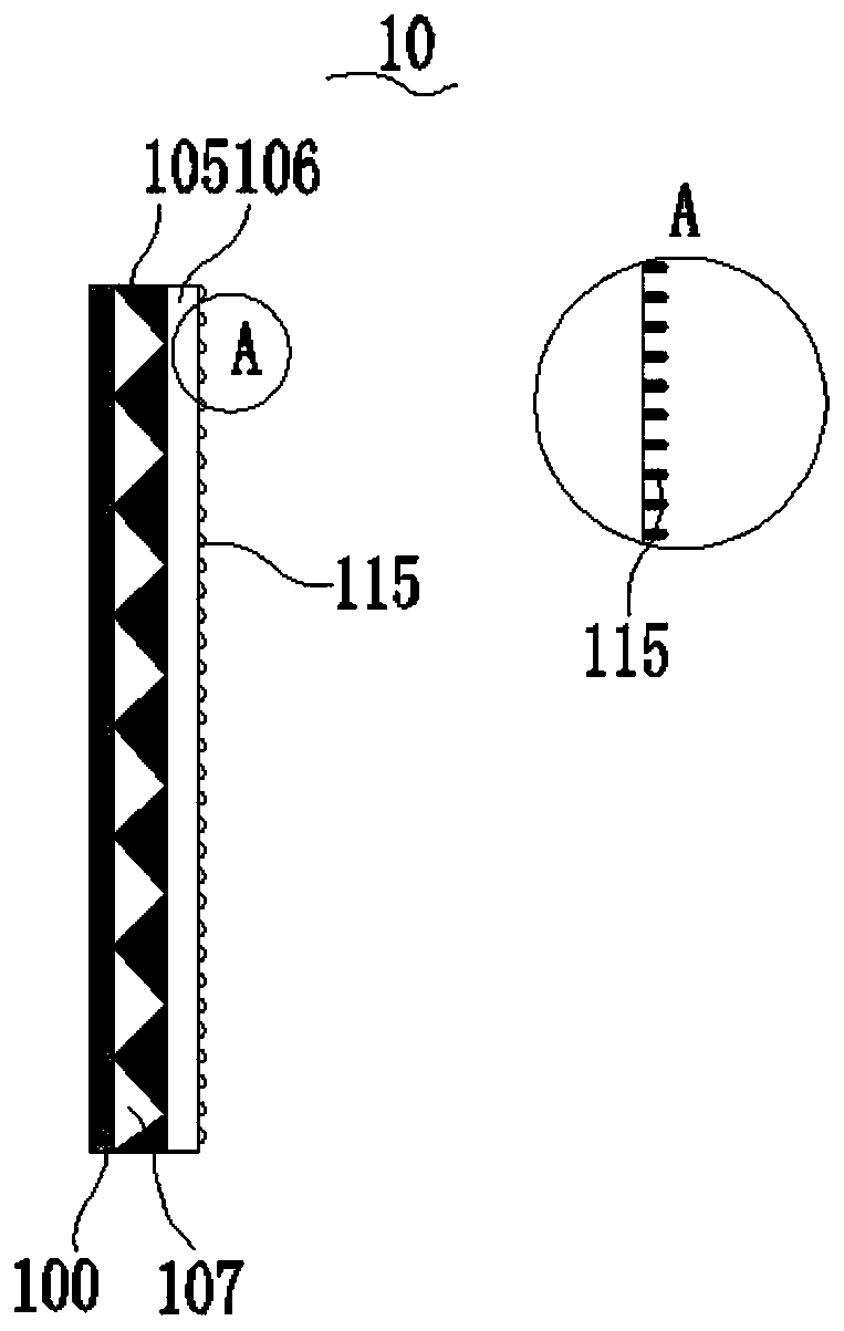
[0053] Such as figure 2 As shown, the embodiment of the present invention provides a projection screen 10, including an imaging layer 100, an optical structure layer 107, and a nanoscale fine structure layer 106 arranged in sequence along the thickness direction; the nanoscale fine structure layer 106 is far away from the optical One side surface of the structural layer 107 is provided with several nanoscale microstructures 115, the cross-section of the optical structural layer 107 in the thickness direction is a number of triangles arranged in rows, and one side of the triangle is arranged on the surface of the imaging layer 100 , the optical structure layer 107 is laminated with the nanoscale fine structure layer 106 through the bonding layer 105; the bonding layer 105 fills the optical structure layer 107 in the thickness direction.

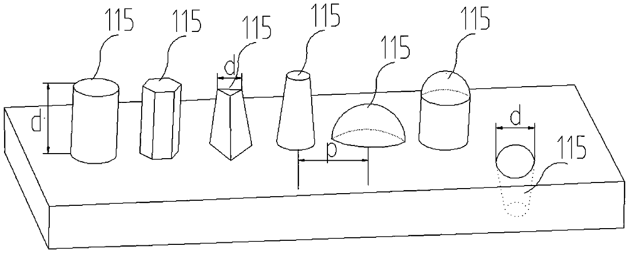
[0054] As an optional manner, the nanoscale fine structure 115 is at least one of a cylinder, a cone, a truncated cone, a truncated prism, a...

Embodiment 2

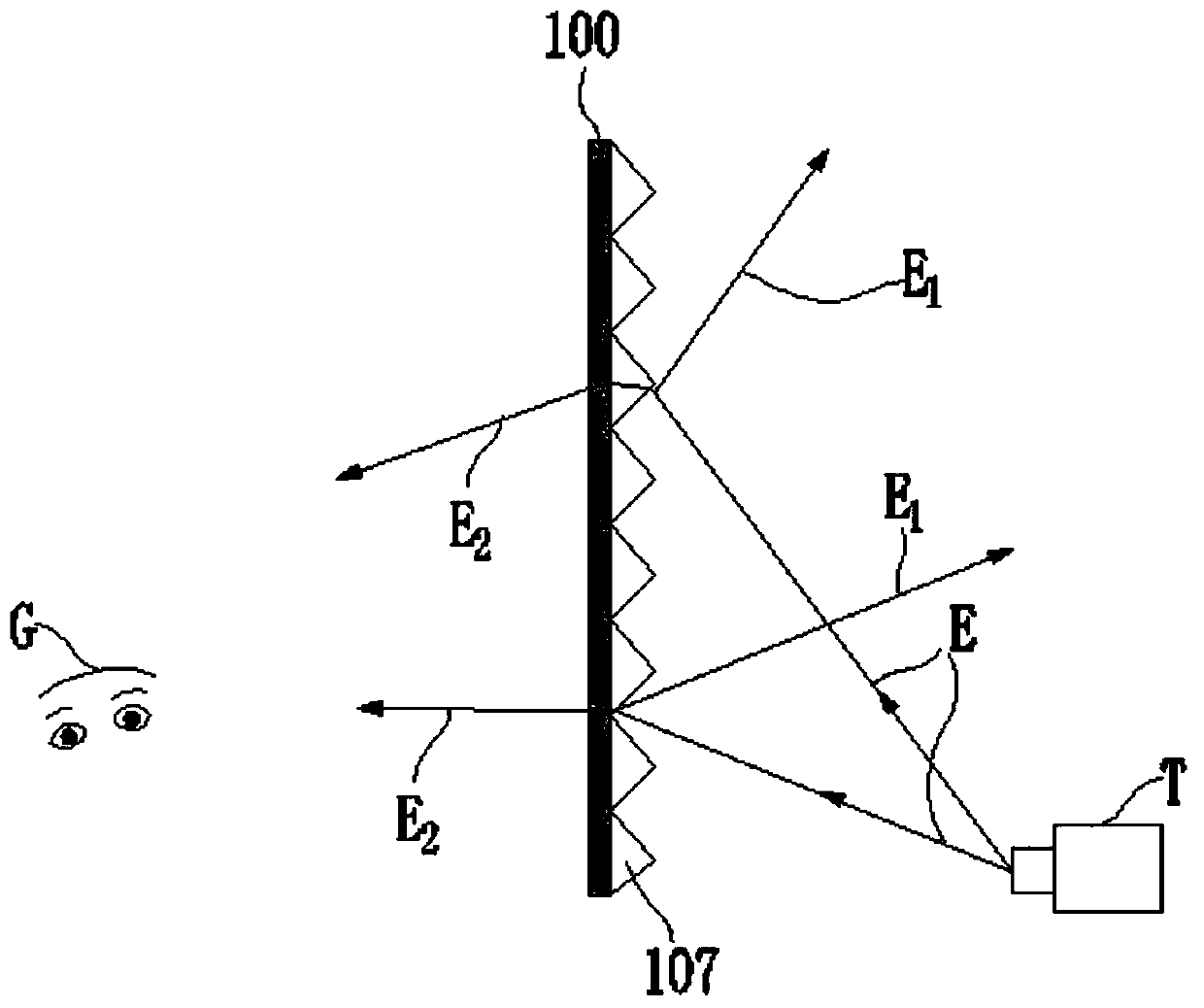
[0087] Such as Figure 27As shown, a projection system 20 includes a projection device T and the rear projection screen according to Embodiment 1 for imaging and displaying based on the projection light beam E output by the projection device T, and the projection device T is arranged on the rear projection screen One side of the nanoscale fine structure 115 of the nanoscale fine structure layer 106 of the screen, the rear projection screen includes an imaging layer 100, an optical structure layer 107 and a nanoscale tie structure layer 106 arranged in sequence along the thickness direction, the nanoscale The surface of the microstructure layer 106 away from the imaging layer 100 is provided with several nanoscale microstructures 115, the nanoscale microstructures 115 are concave structures or convex structures; the cross section of the optical structure layer 107 in the thickness direction is Several rows of triangles arranged mutually, one side of the triangle is arranged on ...


PUM


Abstract

The invention provides a rear projection screen and a projection system, and relates to the technical field of optical projection. The rear projection screen comprises an imaging layer, an optical structure layer and a nanoscale fine structure layer which are sequentially arranged along a thickness direction. A plurality of nanoscale fine structures are arranged on the surface of one side, away from the optical structure layer, of the nanoscale fine structure layer, and the nanoscale fine structures are concave structures or convex structures; a cross section of the optical structure layer inthe thickness direction is a plurality of rows of triangles which are arranged in parallel, one side of each triangle is arranged on the surface of the imaging layer, and the optical structure layer is laminated with the nanoscale fine structure layer through a bonding layer; and the bonding layer fills and levels up the optical structure layer in the thickness direction. The projection system comprises the rear projection screen and a projection device. The rear projection screen and the projection system provided by the invention have advantages of high brightness, a high light energy utilization rate, a high image definition, good ambient light resistance and a high contrast ratio.

Description

technical field [0001] The invention relates to the technical field of optical projection, in particular to a rear projection screen and a projection system. Background technique [0002] With the continuous development of screen display technology, projection has been widely used as a simple and convenient display method, for example, family entertainment or office needs. Among them, when displaying by projection, an indispensable device is a projection screen. The projection screen is composed of a series of fine structures, which can redistribute the light intensity of the projection beam and the ambient light in the screen structure. Its main function is to image the projection beam emitted by the projection device to the audience, effectively shielding the ambient light, enhancing The intensity of light projected by the projection device. Today, as projection display technology is becoming more mature and projection device technology is becoming more and more homogene...

Claims


Application Information

Patent Timeline
Patent Type & Authority Applications(China)
IPC IPC(8): G03B21/56G03B21/60
CPCG03B21/56G03B21/60
Inventor 张益民胡世加
Owner CHENGDU FSCREEN SCI TECH
Why Eureka
Try Eureka