Check patentability & draft patents in minutes with Patsnap Eureka AI!

Three-phase pulse width modulation rectifying circuit and pre-charging method thereof

A technology of pulse width modulation and rectification circuit, which is applied in the direction of electrical components, AC power input conversion to DC power output, output power conversion device, etc., and can solve the problem of complex circuit structure, large input peak current or surge of pre-charging circuit 12 Current, the number of electronic components and other problems, to avoid the input peak current, the number of electronic components is small, the effect of simple control method

Active Publication Date: 2020-05-08
SANTAK ELECTRONICS SHENZHEN
View PDF8 Cites 1 Cited by
  • Summary
  • Abstract
  • Description
  • Claims
  • Application Information

AI Technical Summary

Problems solved by technology

[0004] However, the three-phase pulse width modulation rectifier circuit 1 has one or more of the following defects: the circuit structure of the pre-charging circuit 12 is complex, the number of electronic components is large, and the cost is high
Especially when the voltage of a certain phase of alternating current is too large, a very large input peak current or surge current will be generated in the switch and inductance connected in series with the alternating current of this phase, thus causing damage to the switch

Method used


Image

  • Three-phase pulse width modulation rectifying circuit and pre-charging method thereof
  • Three-phase pulse width modulation rectifying circuit and pre-charging method thereof
  • Three-phase pulse width modulation rectifying circuit and pre-charging method thereof

Examples


Embodiment Construction

[0031] In order to make the object, technical solution and advantages of the present invention clearer, the present invention will be further described in detail below through specific embodiments in conjunction with the accompanying drawings.

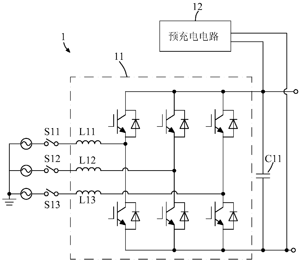
[0032] figure 2 It is a circuit diagram of a three-phase pulse width modulation rectifier circuit according to a preferred embodiment of the present invention. Such as figure 2 As shown, the three-phase pulse width modulation rectifier circuit 2 includes: a three-phase pulse width modulation rectifier 21, which includes three AC input terminals, a positive output terminal 211 and a negative output terminal 212; a first switch S21, a second switch S22 and a second Three switches S33, one end of which is respectively connected to the three AC input terminals of the three-phase pulse width modulation rectifier 21, and the other end is respectively connected to the first-phase alternating current V1, the second-phase alternating current...


PUM


Abstract

The invention provides a three-phase pulse width modulation rectifying circuit and a pre-charging method thereof. The three-phase pulse width modulation rectifying circuit comprises a three-phase pulse width modulation rectifier, a first switch, a second switch, a third switch, a first capacitor, a second capacitor, a first one-way charging branch and a second one-way charging branch, wherein thethree-phase pulse width modulation rectifier includes an input end, a positive electrode output terminal and a negative electrode output terminal; the first switch, the second switch and the third switch are connected between the input end of the three-phase pulse width modulation rectifier and an three-phase alternating current; the first capacitor and the second capacitor are connected in seriesbetween the positive electrode output terminal and the negative electrode output terminal, and a node formed by connecting the first capacitor and the second capacitor is connected to a neutral point; the first one-way charging branch is connected between a first-phase alternating current in the three-phase alternating current and the positive electrode output terminal and is used for pre-charging the first capacitor; and the second one-way charging branch is connected between the first-phase alternating current and the negative electrode output terminal and is used for pre-charging the second capacitor. According to the pre-charging method, an input peak current is prevented from being generated.

Description

technical field [0001] The invention relates to a pulse width modulation rectifier circuit, in particular to a three-phase pulse width modulation rectifier circuit and a precharging method thereof. Background technique [0002] The three-phase pulse width modulation rectifier circuit has the advantages of low grid-side current harmonics, high power factor, bidirectional energy flow, etc., and has been widely used and researched. [0003] figure 1 It is a three-phase pulse width modulation rectification circuit in the prior art. Such as figure 1 As shown, the three-phase pulse width modulation rectifier circuit 1 includes a three-phase pulse width modulation rectifier 11; a first switch S11, a second switch S12 and a third switch S13 connected to the input end of the three-phase pulse width modulation rectifier 11; The capacitor C11 of the output terminal of the three-phase pulse width modulation rectifier 11; The capacitor C11 is charged before the switch S11 , the secon...

Claims


Application Information

Patent Timeline
Patent Type & Authority Applications(China)
IPC IPC(8): H02M7/797H02M1/36
CPCH02M1/36H02M7/797
Inventor 郭晓露张登科张冬宇
Owner SANTAK ELECTRONICS SHENZHEN
Features
  • R&D
  • Intellectual Property
  • Life Sciences
  • Materials
  • Tech Scout
  • Unparalleled Data Quality
  • Higher Quality Content
  • 60% Fewer Hallucinations
Learn More