Eureka AIR delivers breakthrough ideas for toughest innovation challenges, trusted by R&D personnel around the world.

Dust collector speed regulation control system and dust collector

A technology for controlling systems and vacuum cleaners, which is applied in the installation of vacuum cleaners, household appliances, and electrical equipment. It can solve the problems of unfriendly potentiometer speed regulation interface and poor user experience, and achieve the effect of improving experience and smooth stepless speed regulation.

Active Publication Date: 2020-05-12
TIANKE INTELLIGENT TECH CO LTD
View PDF5 Cites 2 Cited by
  • Summary
  • Abstract
  • Description
  • Claims
  • Application Information

AI Technical Summary

Problems solved by technology

[0005] The invention provides a vacuum cleaner speed control system, which is used to solve the problems in the prior art that the potentiometer speed control interface is not friendly and the user experience is poor

Method used


Image

  • Dust collector speed regulation control system and dust collector
  • Dust collector speed regulation control system and dust collector
  • Dust collector speed regulation control system and dust collector

Examples


Embodiment Construction

[0043] In the following description, numerous specific details are set forth in order to provide a thorough understanding of the application. However, the present application can be implemented in many other ways different from those described here, and those skilled in the art can make similar promotions without violating the connotation of the present application. Therefore, the present application is not limited by the specific implementation disclosed below.

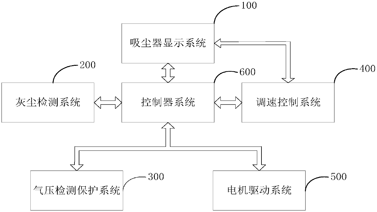
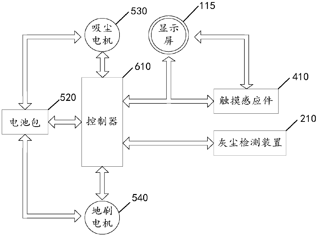
[0044] Please refer to figure 1 with figure 2 , figure 1 It is a logic block diagram among the various systems of the vacuum cleaner of this application; figure 2 It is a logical block diagram of some modules inside the vacuum cleaner of this application;

[0045] The present application provides a handheld vacuum cleaner, including: a vacuum cleaner display system 100 , a dust detection system 200 , an air pressure detection and protection system 300 , a speed control system 400 , a motor drive system 500 and a...


PUM


Abstract

The invention relates to the field of dust collectors, in particular to a dust collector speed regulation control system and a dust collector. The dust collector speed regulation control system comprises a touch sensing part, a second converter, a second controller and a power control device which are electrically connected in sequence; the touch sensing part is arranged on the surface of a dust collector shell; the second converter is used for receiving touch induction electric signals and converting the touch induction electric signals into power indication signals or rotating speed indication signals which can be identified by the second controller; the second controller is used for receiving the power indication signal or the rotating speed indication signal, and generating a power given signal corresponding to the power indication signal or a rotating speed given signal corresponding to the rotating speed indication signal under the control of an internal control element; and thepower control device is used for controlling a motor of the dust collector to move according to the power given signal or the rotating speed given signal. Compared with the prior art, the technical effect of stepless speed regulation on the dust collector is achieved, and the user experience is improved.

Description

technical field [0001] The invention relates to the field of vacuum cleaners, in particular to a vacuum cleaner speed regulation control system and a vacuum cleaner. Background technique [0002] Nowadays, vacuum cleaners are used by more and more families. Vacuum cleaners can assist personnel to effectively clean up and collect small debris or dust. With people's requirements for improving the home environment and changes in consumption concepts, traditional vacuum cleaners are endowed with more and more functions for convenience. people's use. [0003] The main working parts of the vacuum cleaner are ground brushes, dust absorption devices and motors. The principle of its use is to use the motor to run to form a low-pressure area in the dust bucket. According to the air pressure difference inside and outside the dust bucket, dust and other sundries are sucked into the dust bucket through the ground brush, dust absorption device, etc., and the air is purified by the filt...

Claims


Application Information

Patent Timeline
Patent Type & Authority Applications(China)
IPC IPC(8): A47L5/12A47L9/28
CPCA47L5/12A47L9/28
Inventor 孙建
Owner TIANKE INTELLIGENT TECH CO LTD
Why Eureka
Eureka Blog
Learn More