Multifunctional portal magnetic drilling machine

A portable and multi-functional technology, applied in portable drilling rigs, drilling/drilling equipment, parts of boring machines/drilling machines, etc., can solve the problems of poor cooling effect, inconvenient carrying, and unstable work, etc., and achieve the purpose of changing the drilling depth , prevent severe fever, good effect

Inactive Publication Date: 2020-05-12
NORTHWEST A & F UNIV
View PDF0 Cites 1 Cited by
  • Summary
  • Abstract
  • Description
  • Claims
  • Application Information

AI Technical Summary

Problems solved by technology

[0002] Magnetic drill is also called magnetic base drill, magnet drill, magnetic electric drill, iron-absorbing drill, suction drill, suction base drill, and steel plate drill. After electrification, the current changing at the bottom of the magnetic drill generates a magnetic field, which is adsorbed on the steel structure, and then the magnetic drill The motor runs at high speed to drive the drill bit to realize the drilling of the steel structure. However, when the drill rig was used in the past, it was not suitable to be carried to the field for use. It is extremely inconvenient to carry, and the cutter barrel cannot be fixed well during work, resulting in insufficient work. It is stable, and the drilling depth is not easy to adjust, and the cooling effect is poor, which will cause the drill to heat up after a long working time, so we propose this multifunctional portable magnetic drill

Method used


Image

  • Multifunctional portal magnetic drilling machine
  • Multifunctional portal magnetic drilling machine
  • Multifunctional portal magnetic drilling machine

Examples


Embodiment Construction

[0018] In order to make the technical means, creative features, goals and effects achieved by the present invention easy to understand, the present invention will be further described below in conjunction with specific embodiments.

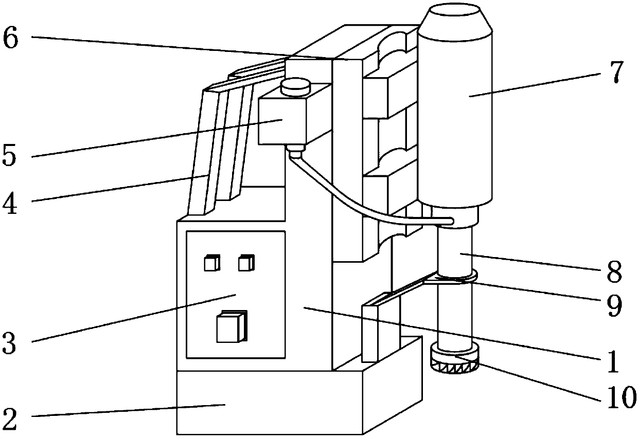
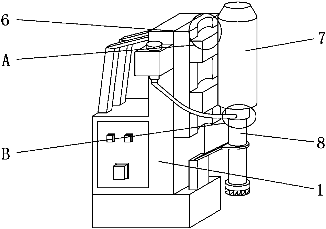
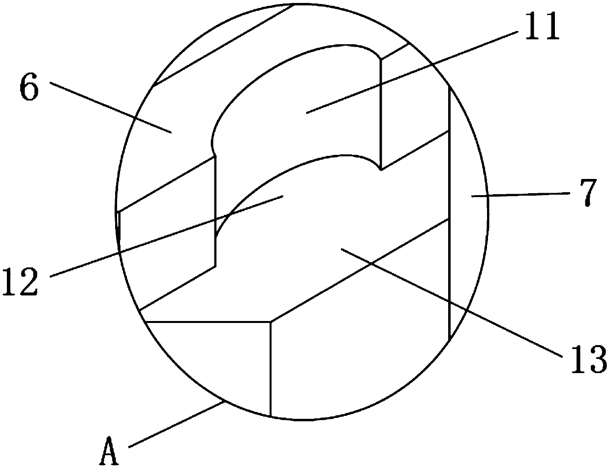
[0019] Such as Figure 1-4 As shown, a multifunctional portable magnetic drill includes a device main body 1, a magnet seat 2 is provided on the outer surface of the lower end of the device main body 1, a cooling oil tank 5 is provided on one side of the front end outer surface of the device main body 1, and a part of the device main body 1 The side outer surface is provided with fixed plate 6, and one side of fixed plate 6 is provided with drive motor 7, and the lower end of drive motor 7 is provided with telescopic knife cylinder 8, and the lower end of telescopic knife cylinder 8 is provided with acupoint drill 10, and the inboard of fixed plate 6 The outer surface is provided with a chute 11, the inner outer surface of the chute 11 is provided...


PUM


Abstract

The invention discloses a multifunctional portal magnetic drilling machine which comprises a device main body, wherein a magnet seat is arranged on the outer surface of the lower end of the device main body; a cooling oil tank is arranged on one side of the outer surface of the front end of the device main body; a fixed plate is arranged on the outer surface of one side of the device main body; adrive motor is arranged on one side of the fixed plate; a telescopic knife cylinder is arranged at the lower end of the drive motor; a hole drill is arranged at the lower end of the telescopic knife cylinder; a sliding chute is formed in the outer surface of the inner side of the fixed plate; a sliding shaft is arranged on the outer surface of the inner side of the sliding chute; and a sliding block is arranged at one end of the sliding shaft. The multifunctional portal magnetic drilling machine utilizes a movable handle to be convenient to carry and suitable for field work, can conveniently adjust the drilling depth, is better in working effect and can prevent the drilling machine from generating excessive heat. The driving record can bring about a better using prospect.

Description

technical field [0001] The invention relates to the technical field of magnetic power drills, in particular to a multifunctional portable magnetic power drill. Background technique [0002] Magnetic drill is also called magnetic base drill, magnet drill, magnetic electric drill, iron-absorbing drill, suction drill, suction base drill, and steel plate drill. After electrification, the current changing at the bottom of the magnetic drill generates a magnetic field, which is adsorbed on the steel structure, and then the magnetic drill The motor runs at high speed to drive the drill bit to realize the drilling of the steel structure. However, when the drill rig was used in the past, it was not suitable to be carried to the field for use. It is extremely inconvenient to carry, and the cutter barrel cannot be fixed well during work, resulting in insufficient work. It is stable, and the drilling depth is not easy to adjust, and the cooling effect is poor, which will cause the drill...

Claims


Application Information

Patent Timeline
Patent Type & Authority Applications(China)
IPC IPC(8): B23B45/02B23B45/14B23B47/26B23Q11/12
CPCB23B45/003B23B45/02B23B47/26B23Q11/126B25H1/0071
Inventor 朱悦马驰蒋宗谨
Owner NORTHWEST A & F UNIV
Why Eureka
Try Eureka