
Rapid replacing device for wellhead blowout preventer

A blowout preventer, fast technology, applied in the field of oil and gas drilling, well completion or pipeline connection, well cementing, can solve the problems of cumbersome, expensive equipment driving, etc., and achieve the effect of low cost and simple structure

Pending Publication Date: 2020-05-12
SOUTHWEST PETROLEUM UNIV
View PDF1 Cites 8 Cited by
  • Summary
  • Abstract
  • Description
  • Claims
  • Application Information

AI Technical Summary

Problems solved by technology

[0006] The purpose of the present invention is to provide a quick replacement device for wellhead blowout preventer, which only needs one hydraulic drive system, in order to solve the problem that the current blowout preventer pipeline connection device needs two hydraulic drive systems, which cause expensive equipment and cumbersome drive The connection lock of the pipeline can be realized

Method used


Image

  • Rapid replacing device for wellhead blowout preventer
  • Rapid replacing device for wellhead blowout preventer
  • Rapid replacing device for wellhead blowout preventer

Examples


Embodiment Construction

[0026] The present invention will be further described in detail below in conjunction with test examples and specific embodiments. However, it should not be understood that the scope of the above subject matter of the present invention is limited to the following embodiments, and all technologies realized based on the content of the present invention belong to the scope of the present invention.

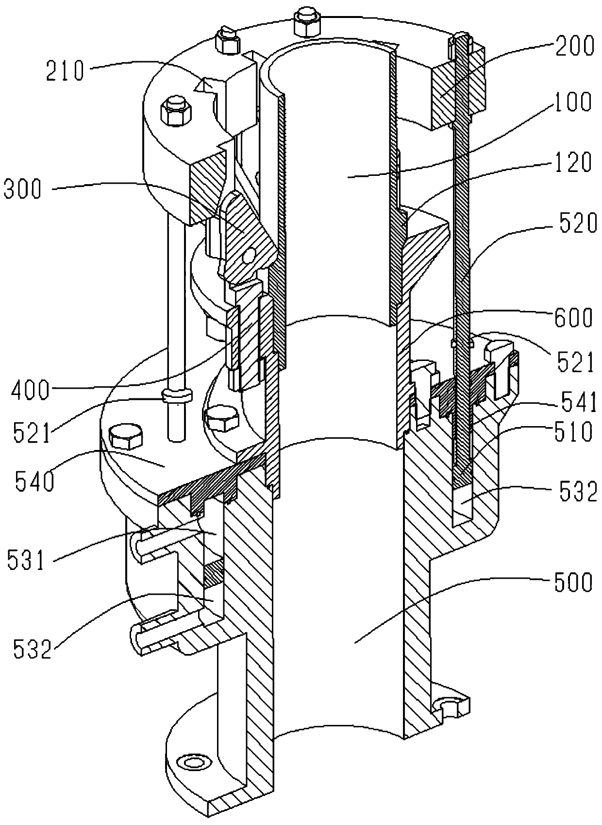
[0027] Such as Figure 2-11 , a quick replacement device for wellhead blowout preventers, including a body pipe 100, a locking ring 200, a cam block 300, a cylinder pipe 500 and a connecting shaft that can rotate around its own axis and is arranged on the body pipe 100 400, the main body pipe 100 is fixedly connected to the coaxial line of the cylinder pipe 500 through the connecting pipe 600, such as figure 2 , the cylinder tube 500 is provided with a piston rod 520 fixedly connected with the locking ring 200, and the piston rod 520 drives the locking ring 200 so that the locking ...


PUM


Abstract

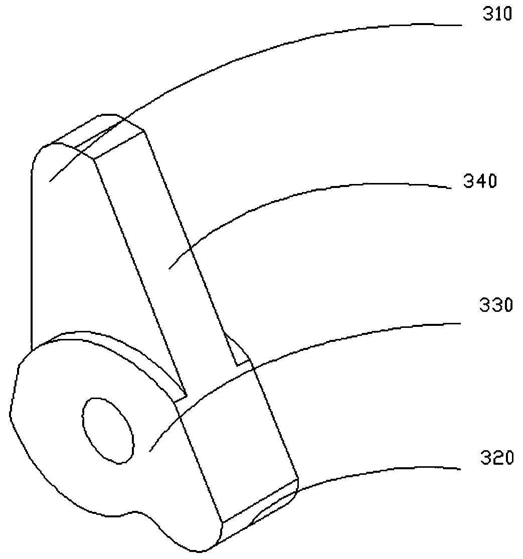
The invention relates to the technical field of oil-gas drilling, well cementation, well completion or pipeline connection, in particular to a rapid replacing device for a wellhead blowout preventer.Grooves for containing cam blocks are formed in the inner side face of a locking ring at intervals, the cam blocks are rotatably arranged on a body pipe, the outer side face of the locking ring comprises a cam bearing surface and a cam locking surface, the cam bearing surface is a protruding curved surface generated by a certain straight section rotating along the rotating center of the cam blocks, and the cam locking surface is a plane. A sliding-in end is located between the cam bearing surface and the cam locking surface in smooth transition. When the cam locking surface is parallel to theaxis of the body pipe, the distance between the cam locking surface and the axis of the body pipe is larger than the radius of a locking-ring locking surface to enable the cam locking surface and thelocking-ring locking surface to be in interference fit, the cam bearing surface extends outwards from top to bottom in the diameter direction of the body pipe, only one hydraulic device is required for driving the locking ring, the structure is simpler, and the cost is low.

Description

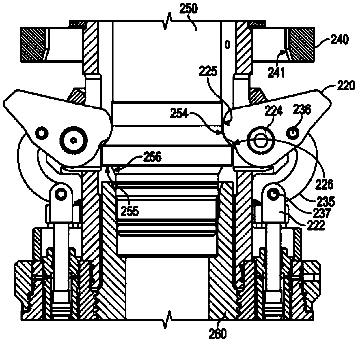
technical field [0001] The invention relates to the technical field of oil and gas drilling, well cementing, well completion or pipeline connection, in particular to a quick replacement device for a blowout preventer at the wellhead. Background technique [0002] Existing device is the U.S. patent of a patent No. US10030461B2, as figure 1 , the cam lock 220 can be opened remotely. First, by remote hydraulic actuation, the camlock piston 222 is pushed to extend, causing the camlock to rotate. The rotation of the cam lock moves the cam lock to the engaged position, so that the contact surface 225 of the cam lock is pressed against a boss 254 connected to the interface pipe 250 of the BOP. Then through the remote hydraulic drive, the piston of the lock ring 240 is retracted, and the lock ring 240 moves down to block the cam lock. The lock ring primarily acts as a safety device to prevent the cam lock from accidentally disengaging in the event of a loss of hydraulic pressure....

Claims


Application Information

Patent Timeline
IPC IPC(8): E21B23/04E21B33/06
CPCE21B23/04E21B33/06
Inventor 胡刚王锐辜思曼刘志伟黄梦婷
Owner SOUTHWEST PETROLEUM UNIV
Learn More