Safety Clutch

A technology of safety clutches and suction discs, applied in clutches, non-mechanical drive clutches, mechanical equipment, etc., can solve problems such as large impact force, reduced gear train life, engine gear train failure, etc., achieve high cooling capacity and ensure normal operation The effect of work

Active Publication Date: 2020-05-12
WEICHAI POWER CO LTD
View PDF7 Cites 3 Cited by
  • Summary
  • Abstract
  • Description
  • Claims
  • Application Information

AI Technical Summary

Problems solved by technology

[0003] At present, most of the multi-stage electromagnetic clutches used in the engine are purely electromagnetically controlled. The suction of the suction plate and the drive plate is realized through electromagnetism. The suction force generated at the moment of suction can reach 10-13KN. It is a non-safety type. When the fan clutch fails, the low-speed rotation of the fan can only be guaranteed by the friction of the bearing, which will easily lead to high water temperature in the cooling system. The locking screw can only be manually locked as a temporary measure. The operation is cumbersome and the time limit is short. causing users to panic
In addition, the huge impact force can easily lead to engine gear train failure, increase the gear train failure rate, and reduce the life of the gear train

Method used


Image

  • Safety Clutch
  • Safety Clutch
  • Safety Clutch

Examples


Embodiment Construction

[0020] In order to make the objectives, technical solutions and advantages of the present invention clearer, the following further describes the present invention in detail with reference to the accompanying drawings and embodiments. It should be understood that the specific embodiments described here are only used to explain the present invention, and are not used to limit the present invention.

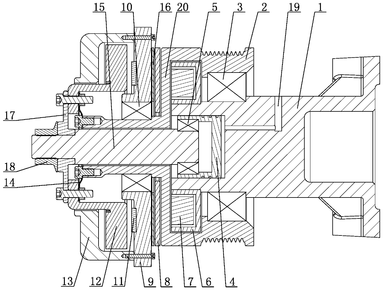
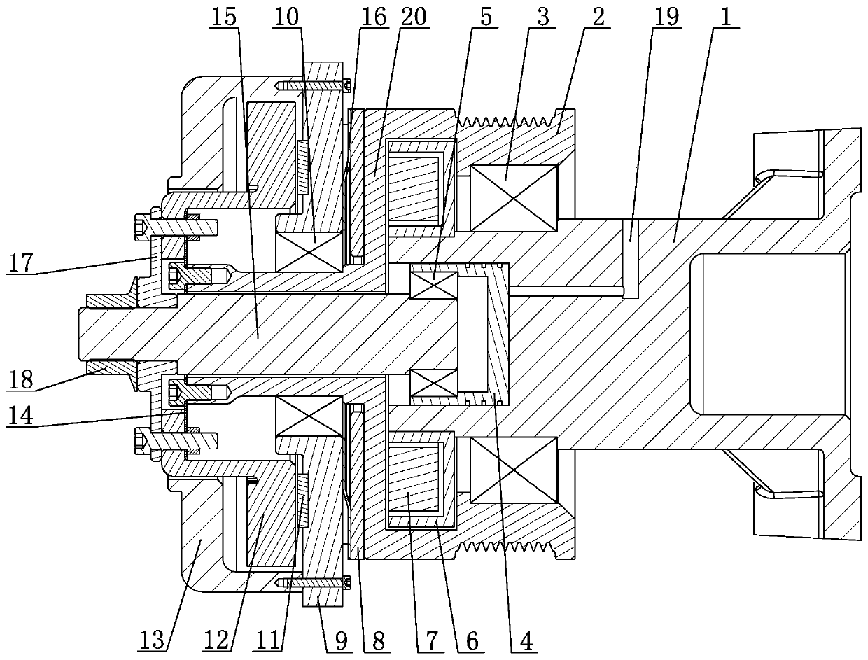
[0021] Such as figure 1 , figure 2 with image 3 As shown together, a safety clutch includes: a bracket 1, a pulley 2, a drive shaft 15, a permanent magnet 11, a coil 7, an iron core 6, a fan fixing plate 13, a cooling plate 12 and a rear cover 9. The pulley 2 passes through a bearing 3 Rotatingly mounted on the bracket 1, the belt pulley 2 is fixedly provided with a transmission disk 20, one side of the transmission disk 20 is provided with a coil 7 and an iron core 6, the iron core 6 is fixed on the outside of the coil 7, and the iron core 6 is fixed on the bracket 1. The other sid...


PUM


Abstract

The invention discloses a safety clutch. The safety clutch comprises a bracket, belt wheels, a transmission shaft, permanent magnets, electromagnets, iron cores, fan fixed plates, heat dissipation plates and rear covers, wherein the belt wheels are rotationally arranged to the bracket by bearings, the belt wheels sleeves the transmission shaft, and the belt wheels are provided with transmission plates; one sides of the transmission plates are provided with coils and the iron cores, and the coils and the iron cores are fixed to the bracket; the other sides of the transmission plates are provided with suction plates, first elastic pieces are fixed between the suction plates and the rear covers, the permanent magnets are fixedly arranged on the sides, far away from the suction plates, of therear covers, and the rear covers are rotationally arranged on the transmission shaft; the rear covers are fixedly connected with the fan fixing plates, the heat dissipation plates are fixedly connected with the transmission shaft, second elastic pieces are fixed between the heat dissipation plates and the belt wheels, and the heat dissipation plates and the permanent magnets are oppositely arranged; and a piston cavity is arranged in the bracket in an erected mode, a piston is arranged in the piston cavity in a sliding mode, and the transmission shaft is rotationally arranged on the piston. The safety clutch realizes flexible control by controlling gaps between the heat dissipation plates and the permanent magnets through the piston, and meanwhile has the function of failure protection.

Description

Technical field [0001] The invention relates to the technical field of engines, in particular to a safety clutch. Background technique [0002] The electromagnetic fan clutch is a device that can control the fan speed through the water temperature. It can be energized and disconnected by the large and small coils to achieve suction and separation. The fan speed can switch between high speed, medium speed and low speed with the water temperature, and the engine water temperature can be controlled at a relative Improve thermal efficiency within a reasonable fluctuation range. Compared with rigid fans, the electromagnetic fan clutch saves energy and reduces consumption, and responds quickly to the silicon oil fan, which makes the electromagnetic fan clutch widely used. [0003] At present, the multi-stage electromagnetic clutch used in the engine is mostly pure electromagnetic control. The suction disc and the drive disc are attracted by electromagnetism. The suction force generated ...

Claims


Application Information

Patent Timeline
Patent Type & Authority Applications(China)
IPC IPC(8): F16D29/00
CPCF16D29/00
Inventor 王剑雄刘健王丽霞刘腾代空军白宇鹏
Owner WEICHAI POWER CO LTD
Why Eureka
Try Eureka