Concrete and preparing system and preparing method thereof

A technology for preparing a system and concrete, which is applied to clay preparation devices, chemical instruments and methods, cement mixing devices, etc., can solve the problems that bagged concrete cannot be evenly turned, and bagged concrete cannot be laid equally, and achieves the effect of being easy to place.

Active Publication Date: 2020-05-15
南京龙航混凝土有限公司
View PDF7 Cites 2 Cited by
  • Summary
  • Abstract
  • Description
  • Claims
  • Application Information

AI Technical Summary

Problems solved by technology

But this patent can't further shake the ba...

Method used


Image

  • Concrete and preparing system and preparing method thereof
  • Concrete and preparing system and preparing method thereof
  • Concrete and preparing system and preparing method thereof

Examples


specific Embodiment approach 1

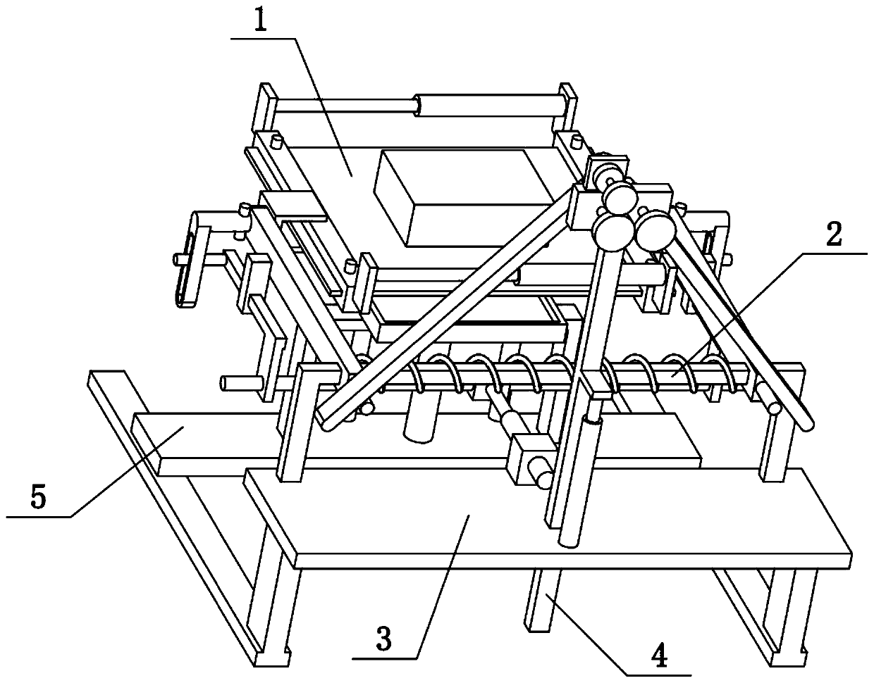
[0035] Combine below Figure 1-10 Describe this embodiment, the present invention relates to the field of concrete preparation, more specifically a concrete preparation system, including textile cloth 1, protruding piece 101, hollow tube 102, solid rod 103 and edge strip 104, the present invention can pack The concrete is further shaken evenly, and the bagged concrete can be paved to facilitate the placement of the bagged concrete.

[0036]There are two side strips 104 left and right, the left and right sides of the textile cloth 1 are respectively inserted on the two side strips 104, and fastening screws are arranged on the two side strips 104 to fix the textile cloth 1 on the side strips 104 , the front and rear ends of the two side bars 104 are fixedly connected with lugs 101, the two lugs 101 at the left end are fixedly connected with a solid rod 103, and the two lugs 101 at the right end are fixedly connected with a hollow cylinder 102, The two solid rods 103 are sliding...

specific Embodiment approach 2

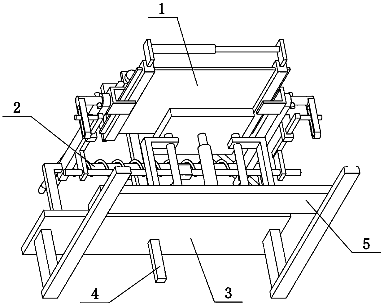
[0038] Combine below Figure 1-10 To illustrate this embodiment, the concrete preparation system further includes a door-shaped piece 105, a stop pin 106, a fixed shaft 107, a cross bar 2 and a left and right moving rod 206, and the outer middle parts of the two side bars 104 are fixedly connected with the door-shaped piece 105 , the outer sides of the two door-shaped parts 105 are fixedly connected with fixed shafts 107, and one end of the two left and right moving rods 206 is respectively slidably connected to the left and right ends of the cross bar 2, and the cross bar 2 between the two left and right moving rods 206 A compression spring is sleeved, and the two fixed shafts 107 are respectively rotatably connected to the front ends of the two left and right moving rods 206, and the two fixed shafts 107 are fixedly connected with stop pins 106, and the two stop pins 106 are respectively located on the two left and right moving rods. 206 outside. The two left and right movi...

specific Embodiment approach 3

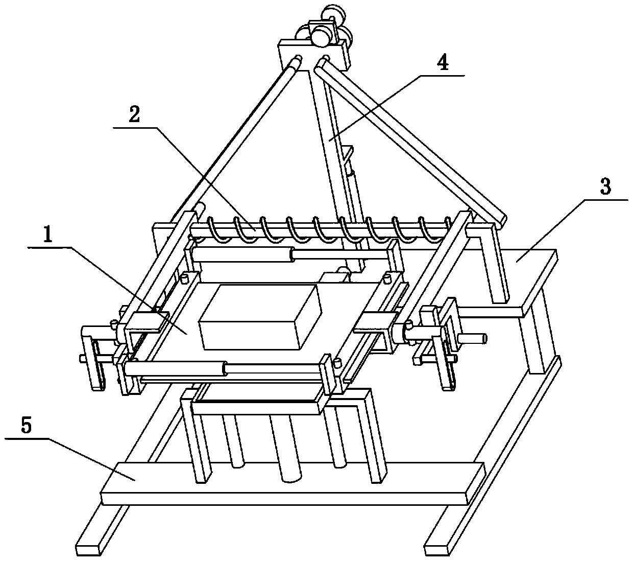
[0040] Combine below Figure 1-10 To illustrate this embodiment, the concrete preparation system also includes a sliding hole rod 108, a sliding hole 109, a pillar 202, a front and rear moving rod 203, a sliding cylinder 204, a fixed seat 205, a flat plate 3, an electric push rod 1301 and a push-pull rod 303. The left and right ends of the rod 2 are fixedly connected with pillars 202, the lower ends of the two pillars 202 are fixedly connected on the flat plate 3, the outer ends of the two fixed shafts 107 are fixedly connected with the sliding hole rods 108, and the two sliding hole rods 108 Sliding holes 109 are arranged on the top, and two fixed seats 205 are fixedly connected on the two left and right moving rods 206. One end of each is fixedly connected with a sliding cylinder 204, and the two sliding cylinders 204 are respectively slidably connected to two sliding holes 109, an electric push rod I301 is fixedly connected to the plate 3, and the other end of the electric ...


PUM


Abstract

The invention relates to the field of concrete preparing, in particular to concrete and a preparing system and a preparing method thereof. The concrete is composed of raw materials including, by weight part, 10 parts of water, 1 part of silica powder, 2 parts of sodium fluosilicate, 4 parts of colemanite, 3 parts of polyurethane particles, 5 parts of metacrylic acid ester, 0.5 part of an excitingagent, 0.5 part of a water reducing agent and 2 parts of mineral powder. The method comprises the steps that firstly, the concrete raw material is placed in a plastic woven bag, and a concrete bag isplaced on textile cloth; secondly, when lower portions of two inclined pressing rods get close to each other, two convex cylinders are pressed to get close to each other, and two left and right movingrods slide on a transverse rod to get close; and thirdly, the lower portions of the two inclined pressing rods are away from each other, due to the effect of a compression spring, the two left and right moving rod rapidly get away, the textile cloth is rapidly changed into the tensioning state, bagged concrete on the textile cloth is topped up rapidly, and the topping up action is repeated continuously.

Description

technical field [0001] The invention relates to the field of concrete preparation, more specifically a concrete and its preparation system and preparation method. Background technique [0002] The patent No. CN201711490866.5 discloses a concrete maker equipped with a blade with holes, and the invention relates to equipment for concrete prefabricated parts. A concrete maker equipped with blades with holes, including a container and a mixing blade, the container is provided with a material inlet hole, a water supply chamber and an intermediate water chamber, the material inlet hole is provided with an annular water outlet channel, and the annular water outlet channel is provided with a water spray hole for water replenishment The chamber communicates with the intermediate water chamber through the first one-way valve, and the intermediate water chamber communicates with the annular water outlet channel through the second one-way valve. An energy recovery structure is arranged ...

Claims


Application Information

Patent Timeline
IPC IPC(8): B28C5/00C04B28/02
CPCB28C5/003B28C5/006C04B28/02C04B18/146C04B22/12C04B14/36C04B16/082C04B24/045C04B18/141C04B2103/0068C04B2103/302
Inventor 王国强
Owner 南京龙航混凝土有限公司
Why Eureka
Try Eureka