Aircraft reconnaissance camera optical axis calibration device and method based on inertial navigation and optical measurement

A technology for optical measurement and calibration devices, applied in the direction of measuring devices, instruments, etc., can solve the problems of low precision, low efficiency, time-consuming and labor-intensive, etc., and achieve the effect of increasing the degree of automation, overcoming interpretation errors, and convenient and quick use

Inactive Publication Date: 2020-05-15
AEROSPACE JINPENG TECH EQUIP (BEIJING) CO LTD
View PDF5 Cites 2 Cited by
  • Summary
  • Abstract
  • Description
  • Claims
  • Application Information

AI Technical Summary

Problems solved by technology

The existing target calibration method is to use the original method of topping the aircraft, aligning, erecting a target or drawing a target map, and then adjusting the target for weapon system target calibration. This method is time-consuming, laborious, low in efficiency, and low in accuracy. The complex structure of the equipment seriously restricts the efficiency of target calibration work, the hit rate of weapons and the speed of dispatching large aircraft groups

Method used


Image

  • Aircraft reconnaissance camera optical axis calibration device and method based on inertial navigation and optical measurement
  • Aircraft reconnaissance camera optical axis calibration device and method based on inertial navigation and optical measurement
  • Aircraft reconnaissance camera optical axis calibration device and method based on inertial navigation and optical measurement

Examples


Embodiment Construction

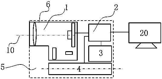
[0039] Such as Figure 1-5 As shown, the comprehensive target calibration system is composed of a comprehensive target calibration instrument host, a main control unit 20, a reference plane mirror 61 and its tooling, a weapon system adapter, a tripod and connecting cables.

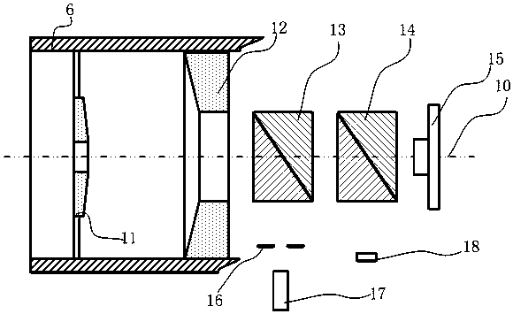
[0040] figure 2 Among them, the host of the comprehensive target calibration instrument includes an optical system 1 installed inside the casing 5, an image processing unit 2, a display screen 3 and an inertial measurement instrument 4; be consistent.

[0041]The optical system 1 comprises a secondary mirror 11, a primary mirror 12, a first cemented half mirror prism 13, a second cemented half mirror prism 14 and an image sensor 15 coaxially arranged in sequence according to the optical axis 10 direction, and the secondary mirror 11 and the primary mirror 12 are both It is a hollow structure, and the focusing lens group is formed on the spatial position; on the reflected light paths of the first cemente...


PUM


Abstract

The invention discloses an aircraft reconnaissance camera optical axis calibration device and method based on inertial navigation and optical measurement. The device comprises a target calibration instrument host and a main control unit, wherein the target calibration instrument host comprises an optical system, an image processing unit and an inertia measuring instrument which are installed in amachine shell; the heading axis direction of the inertia measuring instrument is consistent with the optical axis direction of the optical system; the optical system comprises a light source and a focusing lens group; and the main control unit calculates attitude angle parameters of the optical axis of the reconnaissance camera according to angle data of the inertia measuring instrument and axialdeviation angle data of the image processing unit. According to the invention, the calibration of the axial parallelism of the camera is realized through the combination of the optical system and theinertia measuring instrument, the calibration precision is high, and the use is convenient and fast. The calibration device is not only suitable for aircrafts (helicopters) to use under maintenance and assembly conditions, but also can be used in ship-borne, hangars, strong wind or narrow and messy working spaces.

Description

technical field [0001] The invention belongs to the technical field of weapons and equipment, and relates to an aircraft reconnaissance camera optical axis calibration device and method based on inertial navigation and optical measurement. Background technique [0002] Armed aircraft (helicopters) can carry missiles, rockets, cannons, bombs and other weapons to carry out air strikes on enemy targets. The strike effect depends on the accuracy of the weapon system. However, in actual use, due to the influence of factors such as temperature, shock, vibration and fatigue deformation, the aiming accuracy of the weapon system will change. School, referred to as the school target. [0003] Target calibration is the general term for all calibration and adjustment operations that coordinate the optical, electrical, and mechanical axes of each device in the weapon system with the reference coordinate axis or maintain a certain spatial position relationship. It is a regular, directl...

Claims


Application Information

Patent Timeline
Patent Type & Authority Applications(China)
IPC IPC(8): G01C25/00
CPCG01C25/005
Inventor 周士国冯建新卿宇
Owner AEROSPACE JINPENG TECH EQUIP (BEIJING) CO LTD
Why Eureka
Try Eureka