A micro-lens array element for light spot shaping

A micro-lens array and micro-lens technology, applied in the field of optical lenses, can solve the problems of low light transmission efficiency and difficult spot shape, and achieve the effect of high light efficiency

Inactive Publication Date: 2020-05-15
合肥嘉东光学股份有限公司
View PDF5 Cites 0 Cited by
  • Summary
  • Abstract
  • Description
  • Claims
  • Application Information

AI Technical Summary

Problems solved by technology

[0003] At present, the optical shaping elements on the market can be roughly divided into two categories: one is the ordinary diffuser, which is mainly used for light uniformity, and is realized by using the random concave-convex microstructure on the surface to scatter the light. Low, and it is not easy to form a specific spot shape requirement. The second type is a diffractive optical element, which is a specially designed and processed element using the principle of light diffraction. It is characterized by high light efficiency and can form a specific regular spot shape. Sensitive, often can only be used with a single wavelength laser light source

Method used


Image

  • A micro-lens array element for light spot shaping
  • A micro-lens array element for light spot shaping
  • A micro-lens array element for light spot shaping

Examples


Embodiment

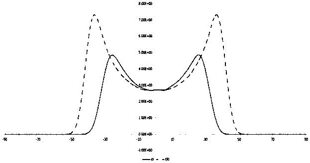
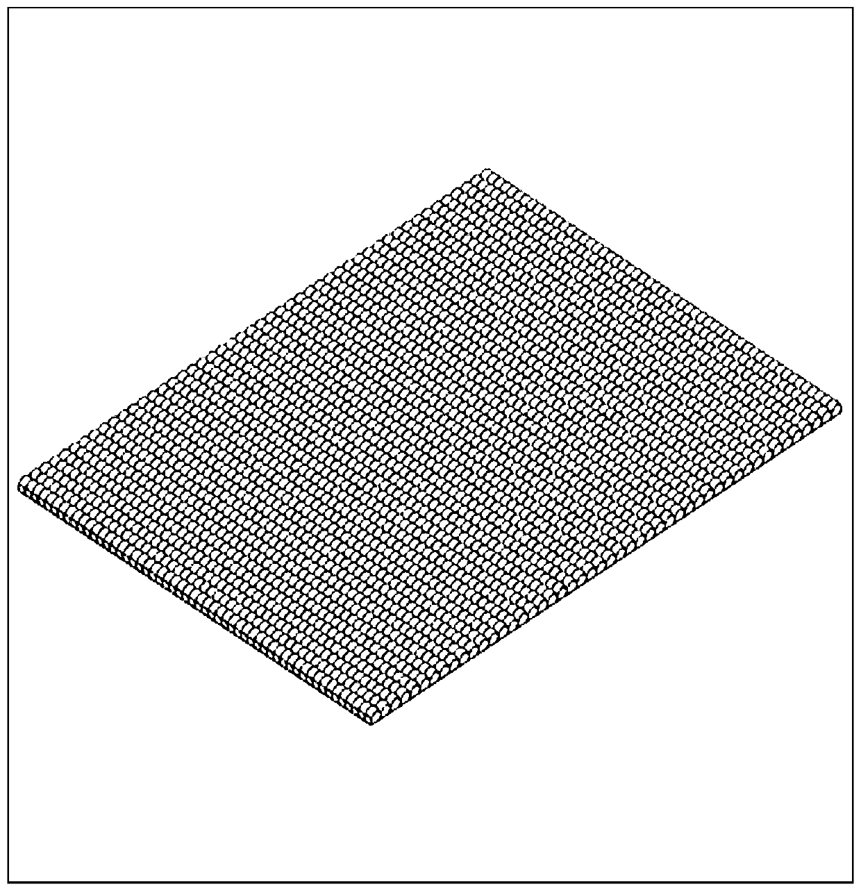
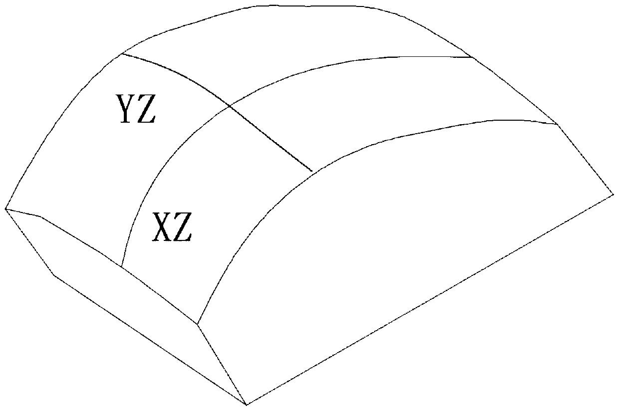
[0039] Embodiment: In the field of 3D recognition of mobile terminals such as mobile phones, rectangular spot lighting is often required. At this time, rectangular micro-lenses can be used for arrangement, such as figure 1 As shown, as an example, the size of each unit here can be 15*22.5 microns, and the shape of each unit microlens refers to the attached figure 2 ,Will figure 2 The unit is repeated to form an attached figure 1 The array element, the microlens of each unit can use the bionic surface to design an effective surface, and the reverse surface of the effective surface can be an ordinary plane or other shape surface, refer to Figure 5 with Image 6 Try to give a special case of surface shape, image 3 In this special case, a vcsel light source is used to illuminate the spot shape, and it can be seen that the effect of a rectangular spot can be better achieved. Figure 4 yes image 3 Intensity distribution curves in two directions of the light spot, the advan...


PUM


Abstract

The invention discloses a micro-lens array element for light spot shaping. The method comprises the following steps: S1, selecting a plurality of proper micro-lens array lenses, S2, selecting the characteristic size of a single micro-lens unit of the micro-lens array in the step S1 to be 10-100 microns; S3, enabling the light energy utilization rate of the single micro-lens array lens element to be greater than 80%; S4, carrying out corresponding sequence arrangement according to actual requirements; S5, after the step S4 is completed, focusing the lens of the micro-lens array on a focal plane; and S6, finally, debugging the finished assembly, designing an effective surface for the micro-lens of each unit by using a bionic surface, preferably processing the micro-lens of each unit by usinga metal mold and a plastic material, and forming a repeated array in which the micro-lenses of each unit are densely arranged. According to the invention, the specially designed regular micro-lens array is adopted, and after the emergent light of the light source passes through the regularly and densely arranged micro-lens array, various special light spot shaping effects can be realized.

Description

technical field [0001] The invention relates to the technical field of optical lenses, in particular to a microlens array element used for shaping light spots. Background technique [0002] With the rapid development of science and technology, the current instruments and equipment have developed towards the trend of optical, mechanical and electrical integration. The optical components manufactured by traditional methods are not only complicated in manufacturing process, but also large in size and heavy in weight. It can no longer meet the needs of today's scientific and technological development. The optical components manufactured by micro-optical technology have become a new development direction because of their advantages of small size, light weight, easy integration and arraying. Microlens array is a kind of micro-optical element widely used at present, and it is widely used in beam shaping, optical device interconnection, three-dimensional imaging and other fields. ...

Claims


Application Information

Patent Timeline
Patent Type & Authority Applications(China)
IPC IPC(8): G02B27/09G02B3/00
CPCG02B3/0037G02B27/0961
Inventor 胡卫东杨利涛唐能
Owner 合肥嘉东光学股份有限公司
Why Eureka
Try Eureka