Selective powder delivery for additive manufacturing

A powder, powder source technology, applied in the field of 3D printing, to achieve the effect of good quality, cost saving, and increase the total production volume

Inactive Publication Date: 2020-05-15
APPLIED MATERIALS INC
View PDF8 Cites 0 Cited by
  • Summary
  • Abstract
  • Description
  • Claims
  • Application Information

AI Technical Summary

Problems solved by technology

Powder flows from the powder source through the nozzle to the top surface

Method used


Image

  • Selective powder delivery for additive manufacturing
  • Selective powder delivery for additive manufacturing
  • Selective powder delivery for additive manufacturing

Examples


Embodiment Construction

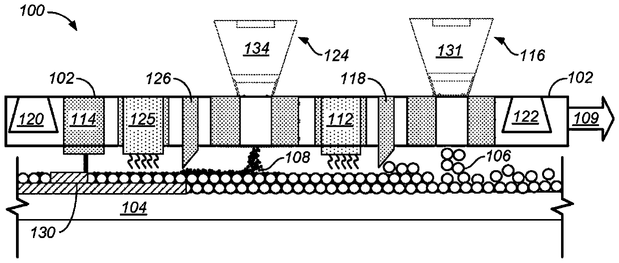
[0034] Additive manufacturing (AM) equipment forms objects by distributing and fusing successive layers of powder on a build platform. It is desirable to control the area on the build table where powder is dispensed on the build table. A controllable dispenser may allow control of the geometry of the object, or simply be used to avoid dispensing powder in areas of the build platform that do not support an object, thereby reducing powder consumption.

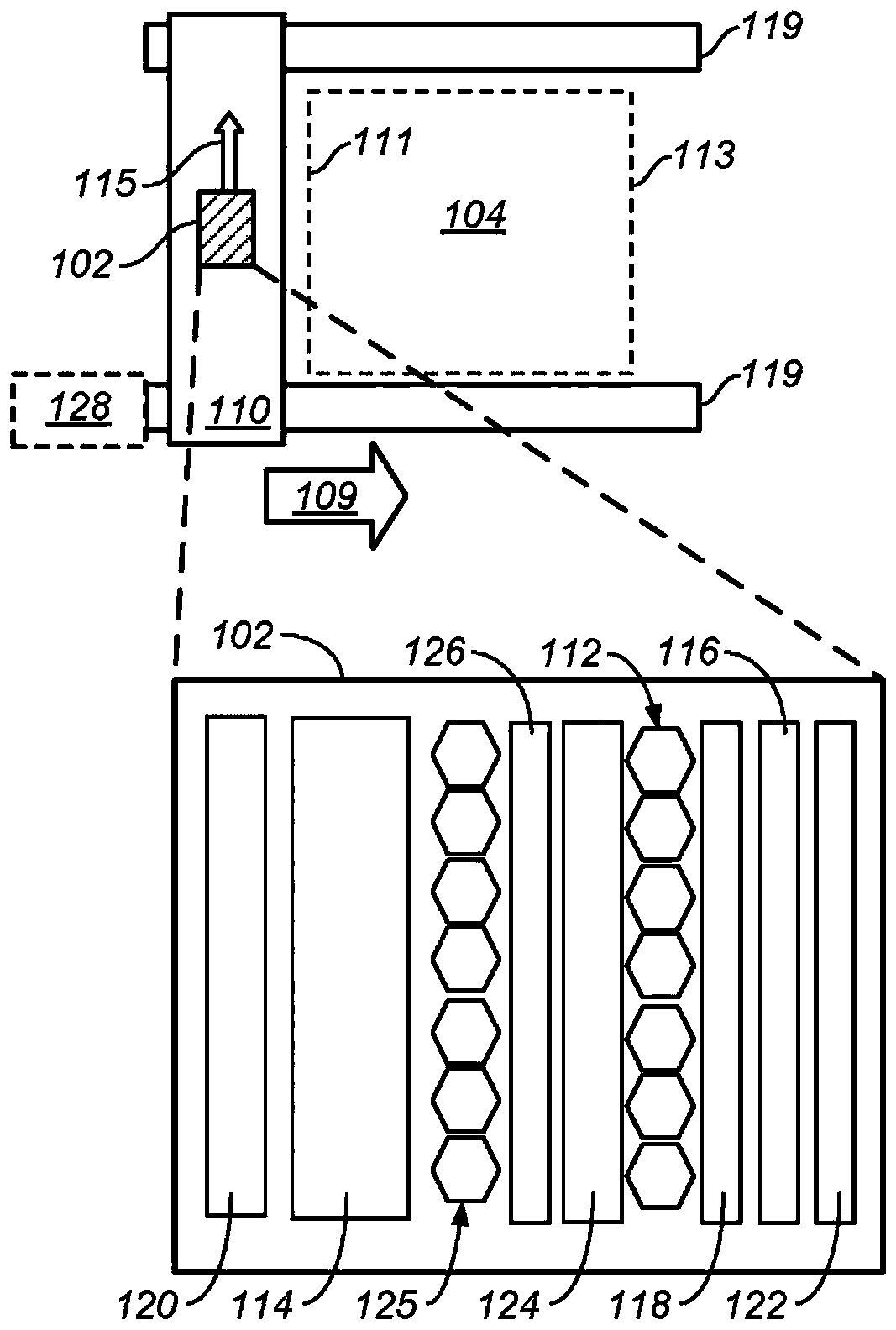
[0035] The dispensing systems described in this specification may include controllable and movable structures that enable the apparatus to selectively dispense powder onto a build platform (also called a platen). Optionally, the controllable and movable structure of the dispensing system also enables control of the powder dispensing rate, selectable for low powder dispensing rates for localized and precise dispensing, or high for high throughput dispensing.

[0036] Additive Manufacturing Equipment

[0037] Figure 1A A schemat...


PUM


Abstract

A dispensing system for an additive manufacturing includes a powder source that contains powder to form an object, and an array of nozzles positioned at a base of the powder source over a top surfaceof a platen where the object is to be formed. The powder flows from the powder source through the nozzles to the top surface. A respective powder wheel in each nozzle controls a flow rate of the powder. Each wheel has multiple troughs on surface of the wheel. When a motor rotates the wheel, the troughs transport the powder through the nozzle. The rotation speed of the wheel controls the flow rate.For solid parts of the object, the wheel rotates and allows the powder to be deposited on the top surface. For empty parts of the object, the wheel remains stationary to prevent the powder from flowing to the surface.

Description

technical field [0001] This brochure is about additive manufacturing, also known as 3D printing. Background technique [0002] Additive manufacturing (AM) (also known as solid free-form manufacturing or 3D printing) refers to the manufacturing process of building three-dimensional objects by sequentially dispensing raw materials (e.g., powders, liquids, suspensions, or molten solids) into two-dimensional layers . In contrast, traditional machining techniques involve ablation processes in which objects are cut from raw materials (eg, blocks of wood, plastic, or metal). [0003] A variety of build-up processes are available in build-up manufacturing. Some methods (eg, selective laser melting (SLM) or direct metal laser sintering (DMLS), selective laser sintering (SLS), fused deposition modeling (FDM) ) melt or soften the material to create layers, while other methods use different techniques (eg, stereolithography (SLA)) to solidify liquid materials. These processes may di...

Claims


Application Information

Patent Timeline
Patent Type & Authority Applications(China)
IPC IPC(8): B22F3/105B33Y10/00B33Y30/00B33Y50/02
CPCB29C64/329B29C64/153B29C64/209B29C64/245B29C64/393B29K2071/00B33Y10/00B33Y30/00B33Y40/00B33Y50/02Y02P10/25B22F12/67B22F12/13B22F10/28B22F12/20B22F12/53B22F12/55B22F12/52B22F12/90B22F12/57B22F10/37B22F12/224B22F12/63B33Y70/00B29C64/336B29C64/343B29C64/371B22F10/00
Inventor 拉南·泽哈维胡·T·额奈格·B·帕蒂班德拉埃里克·恩格阿耶·M·乔希卡西夫·马克苏德保罗·J·斯蒂芬斯
Owner APPLIED MATERIALS INC
Why Eureka
Try Eureka