Optical fiber ribbon, optical cable, and method for manufacturing optical fiber ribbon
A manufacturing method and technology of optical fiber ribbons, applied in the direction of bundled optical fibers, light guides, optics, etc., can solve the problems that optical fiber ribbons cannot meet the manufacturing requirements of large number of cores, high density, and small size at the same time, and achieve the effect of easy winding
- Summary
- Abstract
- Description
- Claims
- Application Information
AI Technical Summary
Problems solved by technology
Method used
Image

Examples
Embodiment 1
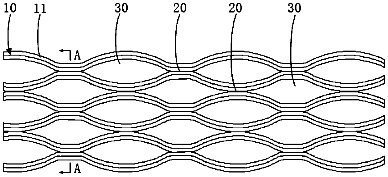
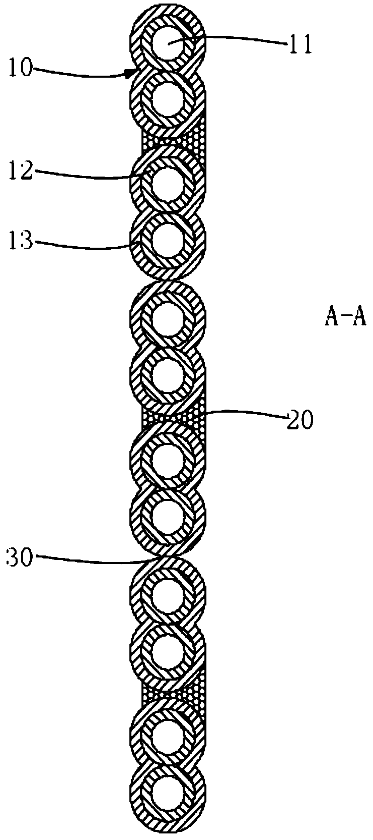
[0044] Such as figure 1 , figure 2 and Figure 7 As shown, the optical fiber ribbon provided by this embodiment includes a plurality of core ribbon sets 10 arranged side by side, and the core ribbon sets 10 are provided with an adhesive part 20 and a separation part 30; the adhesive part 20 and the separation part 30 are spaced along the first direction and Arranged in a staggered manner between any adjacent core band groups 10, and the adhesive part 20 and the separation part 30 are spaced along the second direction and arranged in a staggered manner between any adjacent core band groups 10; the first direction is the core In the lengthwise direction of the belt set 10, the second direction forms an angle with the first direction.
[0045] In this embodiment, the first direction is the length direction of a single core ribbon set 10 , and the second direction is the direction in which multiple core ribbon sets 10 are arranged side by side. Take the formed optical fiber ri...
Embodiment 2
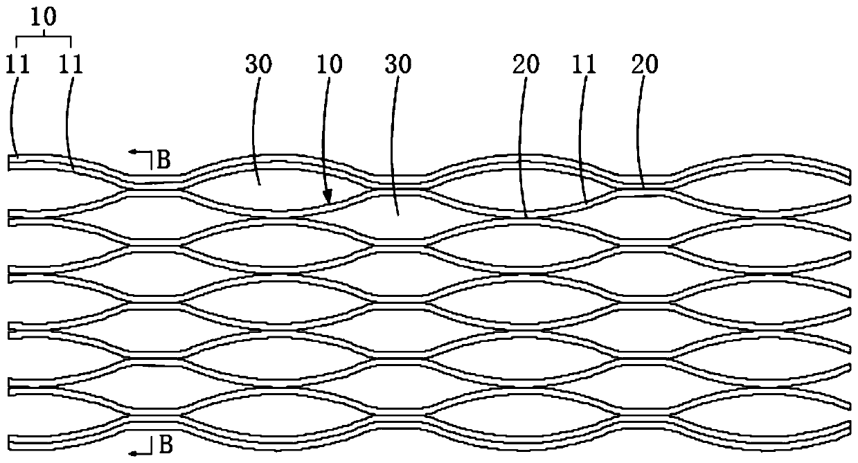
[0062] Please continue to refer image 3 and Figure 4 Preferably, each set of core strips 10 includes one core strip 11 , and the adhesive parts 20 and separation parts 30 are spaced apart and interlaced between any two adjacent core strips 11 .
[0063] In this embodiment, a set of core ribbons 10 includes one core ribbon 11 , and the colored layers 12 outside the core ribbon 11 are used to arrange multiple core ribbons 11 in an orderly manner according to a certain spectral order. Arrange in the longitudinal direction described in Embodiment 1 in the order of the spectrum, then a plurality of core strips 11 are arranged in the longitudinal direction, and adhesive resin is intermittently coated between any two adjacent core strips 11, thereby forming a network fiber optic ribbon.
Embodiment 3
[0065] Please continue to refer Figure 5 and Figure 6 , preferably, the plurality of sets of core ribbons 10 are respectively a first core ribbon set and a second core ribbon set; the first core ribbon set includes a plurality of core ribbons 11 , and the second core ribbon set includes one core ribbon 11 . Both sides of the second core band group along the second direction are respectively provided with the first core band group.
[0066] In this embodiment, there are two sets of first core bands, multiple sets of second core bands, and multiple sets of second core bands are arranged side by side between two sets of first core bands. Each set of second core bands includes a second core band, which is arranged according to the connection method of the single core band 11 in the second embodiment above. Each set of first core bands includes two first core bands, which are arranged according to the connection method of the single core band 11 in the first embodiment above. ...
PUM
| Property | Measurement | Unit |
|---|---|---|
| Outer diameter | aaaaa | aaaaa |
| Length | aaaaa | aaaaa |
| Length | aaaaa | aaaaa |
Abstract
Description
Claims
Application Information
 - R&D Engineer
- R&D Manager
- IP Professional
- Industry Leading Data Capabilities
- Powerful AI technology
- Patent DNA Extraction
Browse by: Latest US Patents, China's latest patents, Technical Efficacy Thesaurus, Application Domain, Technology Topic.
© 2024 PatSnap. All rights reserved.Legal|Privacy policy|Modern Slavery Act Transparency Statement|Sitemap