Highly waterproof liquid crystal display screen assembly

A liquid crystal display and liquid crystal display technology, which is applied in the direction of electrical components, electrical equipment structural parts, instruments, etc., can solve problems that affect the normal operation of electronic components, affect the normal operation of liquid crystal displays, short circuit or rust of electronic components, etc.

Active Publication Date: 2020-05-19
江西慧勤光电科技有限公司
View PDF11 Cites 1 Cited by
  • Summary
  • Abstract
  • Description
  • Claims
  • Application Information

AI Technical Summary

Problems solved by technology

[0003] There are many electronic components inside the liquid crystal display. Once a water ingress accident occurs, it will easily lead to short circuit or corrosion of the electronic components. Therefore, the waterproof measures of the liquid crystal display are an important part of the normal operation of the liquid crystal display. It is also becoming more and more sophisticated, there are basically no gaps between the components, and there will be basically no water ingress accidents. However, during the normal operation of the electronic components inside the LCD display, a large amount of heat will be generated. If the heat is not dissipated in time , the heat will increase the working temperature of the above-mentioned electronic components, which will easily affect the normal operation of the electronic components and even reduce the service life of the electronic components. Therefore, the liquid crystal display usually has cooling holes for heat dissipation, and the external liquid water Once it enters the liquid crystal display through these cooling holes, it will easily lead to short circuit or corrosion of electronic components, which will affect the normal operation of the liquid crystal display.

Method used


Image

  • Highly waterproof liquid crystal display screen assembly
  • Highly waterproof liquid crystal display screen assembly
  • Highly waterproof liquid crystal display screen assembly

Examples


Embodiment 1

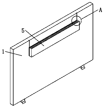
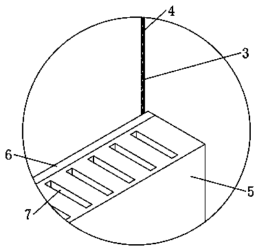
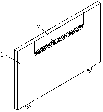
[0032] see Figure 1-5 and Figure 7-8, a highly waterproof liquid crystal display assembly, comprising a liquid crystal display main body 1, a display cooling hole 2 is dug on the liquid crystal display main body 1, and a waterproof box 5 matching the display cooling hole 2 is provided on one side of the liquid crystal display main body 1, The upper end of the waterproof box 5 is dug with a through hole 7, and the liquid crystal display main body 1 is dug with a T-shaped chute 3, and the end of the waterproof box 5 close to the liquid crystal display main body 1 is fixedly connected with a sealing gasket 6 matching the T-shaped chute 3 , the liquid crystal display main body 1 and the waterproof box 5 are slidingly connected through the T-shaped chute 3 and the T-shaped slider 8, and the waterproof box 5 is fixedly connected with a partition plate 9, and the partition plate 9 divides the inside of the waterproof box 5 into fixed parts. There are two parts, the fixed cavity an...


PUM


Abstract

The invention discloses a highly waterproof liquid crystal display screen assembly, and belongs to the field of liquid crystal display components. According to the assembly, in a normal working process of a liquid crystal display body, hot air in a waterproof box can normally exchange heat with external air, and at the moment, the heat dissipation effect is the best, electronic elements in the liquid crystal display main body are in an optimal working state; when a water inlet accident occurs in the waterproof box through a through hole, the lower side space of a partition plate exchanges heatwith the outside through a sliding rod, and at the moment, the heat dissipation effect is worst, however, the heat accumulated in the waterproof box does not easily influence the normal work; along with the increase of the sealing time of sealing holes, the accumulated heat in the waterproof box is increased, at the moment, gas in the waterproof box can exchange heat with the outside through auxiliary heat dissipation holes in a heat dissipation pipe, the heat dissipation effect is good, the accumulated heat in the waterproof box is greatly reduced, and the waterproof effect of the liquid crystal display body is greatly improved.

Description

technical field [0001] The invention relates to the field of liquid crystal display components, in particular to a highly waterproof liquid crystal display component. Background technique [0002] Liquid crystal display is an active-matrix liquid crystal display driven by thin-film transistors (TFT). It mainly stimulates liquid crystal molecules with current to generate points, lines, and surfaces to form a picture with the back lamp tube. IPS, TFT, and SLCD all belong to the sub-categories of LCD. The working principle of liquid crystal display is: under the action of electric field, the arrangement direction of liquid crystal molecules is changed to change (modulate) the light transmittance of the external light source to complete the electro-optical conversion. , and then use the different excitations of the R, G, and B three primary color signals to complete the color reproduction in the time domain and space domain through the red, green, and blue three primary color fi...

Claims


Application Information

Patent Timeline
IPC IPC(8): G09F9/35H05K7/20
CPCG09F9/35H05K7/20954
Inventor 不公告发明人
Owner 江西慧勤光电科技有限公司
Why Eureka
Try Eureka