
Ceramic cover spin riveting machine

A technology of spin riveting machine and spin riveting mechanism, which is applied in the direction of relays, electrical components, circuits, etc., can solve the problems of cumbersome production, increased cost, and uneven product quality, and achieve the effect of preventing tilting and improving assembly accuracy

Pending Publication Date: 2020-05-19
XIAMEN BOAOTE AUTOMATION TECH CO LTD
View PDF0 Cites 0 Cited by
  • Summary
  • Abstract
  • Description
  • Claims
  • Application Information

AI Technical Summary

Problems solved by technology

[0008] The invention provides a ceramic cover riveting machine for producing high-voltage DC relays with high degree of automation, high production efficiency, stable product quality and superior comprehensive performance to solve the problem of low production efficiency and high cost caused by the existing cumbersome production. Welding cannot guarantee the consistent height and position of the leading end during welding, resulting in inconsistent product quality, high labor requirements, further increased costs, and manual work causing physical damage and other technical problems

Method used


Image

  • Ceramic cover spin riveting machine
  • Ceramic cover spin riveting machine
  • Ceramic cover spin riveting machine

Examples


Embodiment Construction

[0049] It should be noted that, in the case of no conflict, the embodiments in the present application and the features in the embodiments can be combined with each other. The present invention will be described in detail below with reference to the accompanying drawings and examples.

[0050] It should be noted that the terminology used here is only for describing specific implementations, and is not intended to limit the exemplary implementations according to the present application. As used herein, unless the context clearly dictates otherwise, the singular is intended to include the plural, and it should also be understood that when the terms "comprising" and / or "comprising" are used in this specification, they mean There are features, steps, operations, means, components and / or combinations thereof.

[0051] It should be noted that the terms "first" and "second" in the description and claims of the present application and the above drawings are used to distinguish simila...


PUM


Abstract

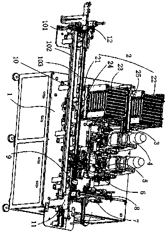
The invention discloses a ceramic cover spin riveting machine which comprises a rack, a ceramic cover feeding mechanism, a ceramic cover transfer mechanism, a spin riveting mechanism, a ceramic covercarrying mechanism, a first detection mechanism, a turnover mechanism, a second ceramic cover discharging mechanism, an assembly righting mechanism, an assembly backflow mechanism and a finished product discharging mechanism, wherein the ceramic cover feeding mechanism, the ceramic cover transfer mechanism, the spin riveting mechanism, the ceramic cover carrying mechanism, the first detection mechanism, the turnover mechanism, the second ceramic cover discharging mechanism, the assembly righting mechanism, the assembly backflow mechanism and the finished product discharging mechanismare arranged on the rack. Theceramic cover feeding mechanism, the ceramic cover transfer mechanism, the spin riveting mechanism, the first detection mechanism and the turnover mechanism are sequentially arranged along a ceramic cover assembling moving direction. The ceramic cover carrying mechanism is arranged in front of the spin riveting mechanism; the second ceramic cover discharging mechanism is locatedabove the overturning mechanism; the assembly backflow mechanism is arranged in front of the ceramic cover carrying mechanism; the assembly righting mechanism is arranged on the assembly backflow mechanism; and the finished product discharging mechanism is arranged at one end of the assembly backflow mechanism. The machine has characteristics of a high automation degree, cost saving, simple operation, high production and work efficiency and the like.

Description

technical field [0001] The invention relates to the technical field of relay production equipment, in particular to a ceramic cover riveting machine for producing high-voltage direct current relays. Background technique [0002] The current DC contactors on the market usually include a ceramic cover and a lead-out terminal. Specifically, the ceramic cover is made of ceramic material, and the lead-out end is made of metal material. The lead-out end is used to install the static contact, and a through hole for installing the lead-out end is correspondingly provided on the ceramic cover. Between the inner cavity of the ceramic cover and the outer space, one end of the leading end extends into the inner cavity of the ceramic cover through the through hole, and the other end of the leading end remains in the outer space of the ceramic cover, and the leading end needs to be fixed on the ceramic cover. cover. The fixing of the ceramic cover and the lead-out end of the DC contacto...

Claims


Application Information

Patent Timeline
IPC IPC(8): H01H49/00
CPCH01H49/00
Inventor 晏吉坤
Owner XIAMEN BOAOTE AUTOMATION TECH CO LTD
Learn More