Oil cooling structure of permanent magnet synchronous motor

A permanent magnet synchronous motor and oil cooling technology, which is applied in the direction of electrical components, electromechanical devices, electric components, etc., can solve problems such as low cooling efficiency, achieve smooth oil output, good cooling effect, and obvious improvement

Inactive Publication Date: 2020-05-19
HEFEI JUYI POWER SYST CO LTD
View PDF7 Cites 10 Cited by
  • Summary
  • Abstract
  • Description
  • Claims
  • Application Information

AI Technical Summary

Problems solved by technology

[0006] The object of the present invention is to provide an oil cooling structure for a permanent magnet synchronous motor, which solves the problem of low cooling efficiency caused by the oil cooling structure due to poor coordination of oil passages

Method used


Image

  • Oil cooling structure of permanent magnet synchronous motor
  • Oil cooling structure of permanent magnet synchronous motor
  • Oil cooling structure of permanent magnet synchronous motor

Examples


Embodiment Construction

[0024] Preferred embodiment of the present invention:

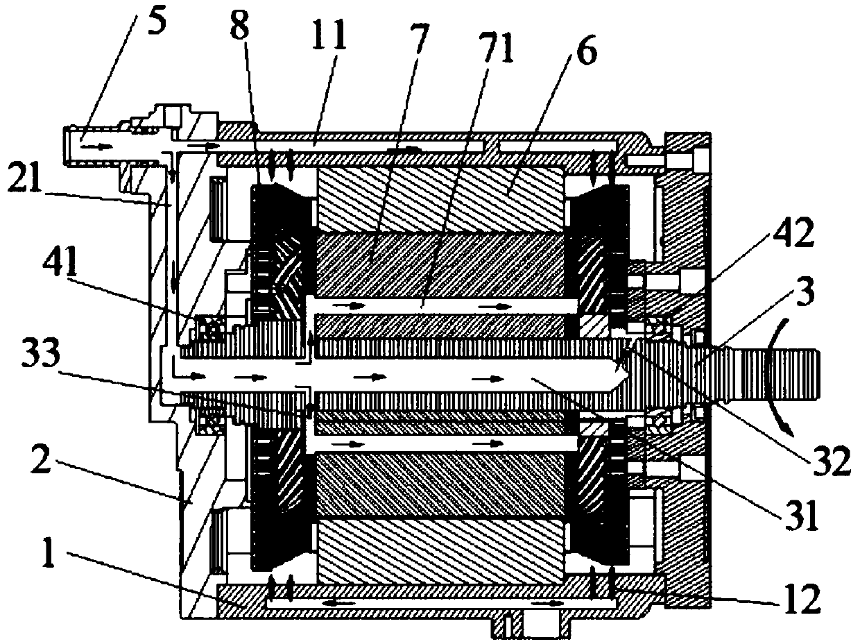
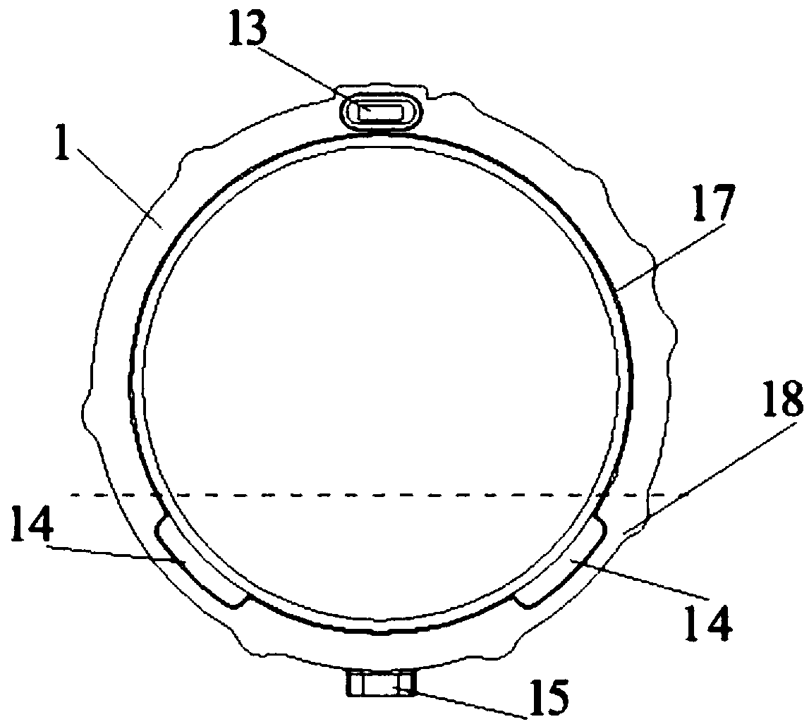
[0025] An oil-cooled structure of a permanent magnet synchronous motor, comprising a motor casing 1 , a motor end cover 2 , a rotating shaft 3 , a motor rotor 7 , and a motor stator 6 . The motor rotor 7 is set on the rotating shaft 3, and the motor winding 8 is embedded on the motor rotor. The corresponding motor stator 6 is arranged inside the motor housing 1, and the rotating shaft 3 is fitted in the motor housing 1 in a coaxial positional relationship. The two ends of the motor housing 1 are respectively sealed with motor end covers 2, and the motor shaft 3 cooperates with the shaft holes on the motor end covers 2 on both sides through the motor bearings.

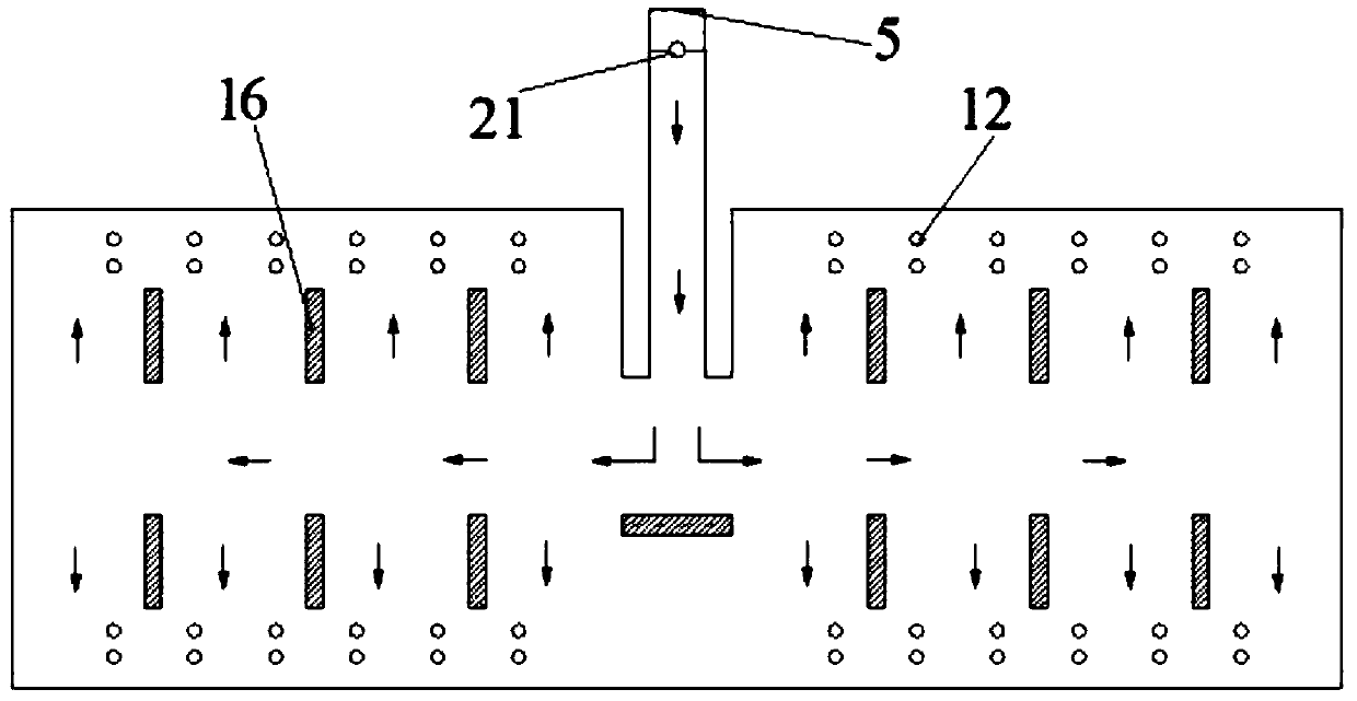
[0026] The inner wall of one of the motor end caps 2 is provided with an end cover oil passage 21, the inner wall of the motor housing 1 is provided with a housing oil passage 11, the axis of the rotating shaft 3 is provided with a rotating shaft 3 oil passages, an...


PUM


Abstract

The invention discloses an oil cooling structure of a permanent magnet synchronous motor, which is characterized in that a rotating shaft provided with a motor rotor is matched in a motor shell through a motor bearing, and the end part of the motor shell is provided with a motor end cover; the motor shell is provided with a shell oil duct; the motor end cover is provided with an end cover oil duct; the rotating shaft is provided with a rotating shaft oil duct; the motor rotor is provided with a rotor oil guide channel; a shell oil duct with an oil inlet function is arranged in the upper shell;a shell oil passage with an oil outlet function is arranged in the lower shell; a shell oil inlet of a shell oil duct with an oil inlet function is formed in the end surface of the upper shell; the lower shell is provided with a motor oil outlet of a shell oil duct with an oil outlet function; the inner wall of the lower shell is provided with a cooling oil recovery port communicating with a shell oil passage with an oil outlet function; the end cover oil duct communicates with the shell oil inlet and the rotating shaft oil duct; the rotating shaft is provided with a rotor oil inlet hole communicating with the rotating shaft oil channel and the rotor oil guide channel. The rotating shaft oil duct leads to the end outlet of the motor rotor; the motor rotor is also provided with a bearing oil injection hole which communicates with the rotating shaft oil channel and faces the motor bearing.

Description

technical field [0001] The invention relates to a motor oil cooling scheme, in particular to an oil cooling structure of a permanent magnet synchronous motor. Background technique [0002] At present, new energy vehicle drive motors are gradually tending to high power density and high speed, and the problem of motor cooling is becoming more and more prominent. Traditional drive motors adopt water cooling or air cooling. Internal or surface cooling media carry heat away. [0003] Existing water-cooled or air-cooled motors can still meet the heat dissipation requirements for motors with low power density. The rotor is effectively cooled, and the power loss of the motor is serious when it runs at high speed for a long time. [0004] For example, the Chinese utility model patent "Cooling structure of oil-cooled motor", application number 2017208136070, discloses an oil passage structure arranged in the end cover of the motor and leading to the fitting gap of the bearing. Alth...

Claims


Application Information

Patent Timeline
Patent Type & Authority Applications(China)
IPC IPC(8): H02K5/20H02K9/19
CPCH02K5/20H02K9/19
Inventor 刘蕾江超田旭刘杰
Owner HEFEI JUYI POWER SYST CO LTD
Why Eureka
Try Eureka