Stator modular double-rotor doubly salient permanent magnet motor

A double-rotor, double-convex technology, applied in electrical components, electromechanical devices, etc., to achieve the effect of facilitating heat dissipation, reducing winding difficulty, improving utilization rate and motor torque density

Inactive Publication Date: 2020-05-19
NANJING UNIV OF AERONAUTICS & ASTRONAUTICS
View PDF5 Cites 1 Cited by
  • Summary
  • Abstract
  • Description
  • Claims
  • Application Information

AI Technical Summary

Problems solved by technology

[0003] In order to solve the technical problems mentioned in the above-mentioned background technology, the present invention proposes a stator modular double-rotor double-convex permanent magnet mo

Method used


Image

  • Stator modular double-rotor doubly salient permanent magnet motor
  • Stator modular double-rotor doubly salient permanent magnet motor
  • Stator modular double-rotor doubly salient permanent magnet motor

Examples


Example Embodiment

[0024] Example 1

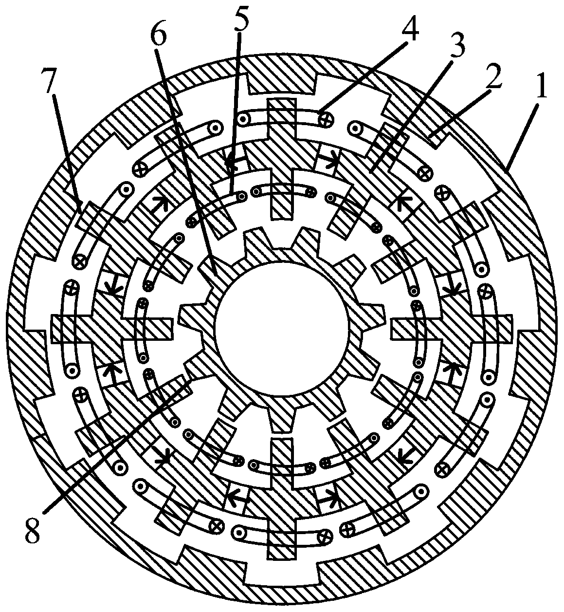
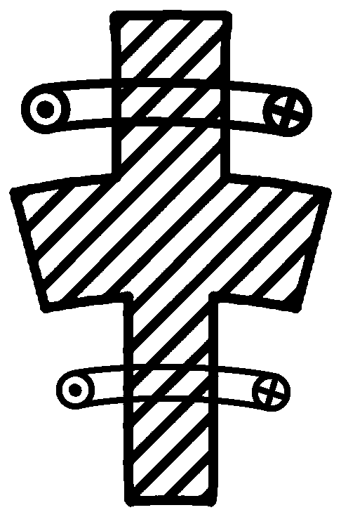
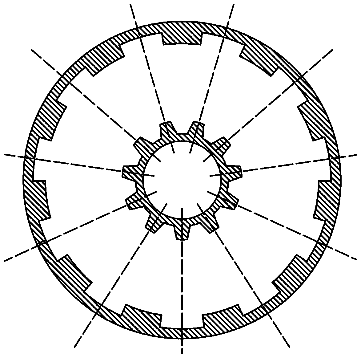
[0025] Such as figure 1 As shown, a stator modular dual-rotor double-convex permanent magnet motor includes an inner salient pole rotor 6, an outer salient pole rotor 1, and a stator located between the two, the inner salient pole rotor 6 and the outer salient pole rotor 1 Separate air gaps 8 and 7 are formed between the stator and the stator. The stator includes several stator modules 3, such as figure 2 As shown, each stator module 3 includes a stator yoke and outer stator teeth and inner stator teeth respectively connected to the outer and inner sides of the middle position of the stator yoke. The stator yokes of each stator module are connected by permanent magnets to form a complete stator. . Armature windings 5 ​​and 4 are wound on the outer stator teeth and the inner stator teeth of each stator module. Such as image 3 As shown, the number of pole pairs of the inner salient pole rotor is the same as that of the outer salient pole rotor (that is, the t...

Example Embodiment

[0030] Example 2

[0031] In order to simplify the processing and assembly process and improve the torque density and fault tolerance of the motor, the stator module in this embodiment adopts Image 6 The structure shown, the structure of the inner and outer salient pole rotor of the motor and the corresponding way of the inner and outer cogging image 3 be consistent. The armature winding connection of the inner and outer stators of the motor is as follows Figure 7 Shown, with Figure 4 The only difference is that armature windings are no longer wound on the inner and outer stator teeth at the connection of each stator module, and the winding direction and sequence of the coils on the remaining inner and outer stator teeth are the same as Figure 4 No difference. The winding connection method can realize the physical isolation between the winding phases and improve the reliability of the motor operation. In addition, the stator teeth with armature windings can also adopt a lar...


PUM


Abstract

The invention discloses a stator modular double-rotor doubly salient permanent magnet motor, which comprises an inner salient pole rotor, an outer salient pole rotor and a stator located between the inner salient pole rotor and the outer salient pole rotor, wherein independent air gaps are formed between the inner salient pole rotor and the stator and between the outer salient pole rotor and the stator respectively; the stator comprises a plurality of stator modules, each stator module comprises a stator yoke part, outer stator teeth and inner stator teeth, the outer stator teeth and the innerstator teeth are connected with the outer side and the inner side of the middle position of the stator yoke part respectively, and the stator yoke parts of the stator modules are connected through permanent magnets to form a complete stator; armature windings are wound on the outer stator teeth and the inner stator teeth of each stator module; and positive and negative alternating counter electromotive forces are induced in armature windings of the inner and outer stators of the motor along with synchronous rotation of the inner and outer rotors and change of relative positions of the stators. The problem of serious stator side flux leakage of the traditional single-rotor doubly salient permanent magnet motor is solved, and the permanent magnet utilization rate and the motor torque density are improved.

Description

technical field [0001] The invention belongs to the field of permanent magnet motors, in particular to a dual-rotor double-convex permanent magnet motor. Background technique [0002] Both the permanent magnet and the armature winding of the biconvex permanent magnet motor are located on the stator, which is easy to realize the cooling of the winding and permanent magnet, and it is easy to realize the temperature rise control of the motor to ensure the reliable operation of the motor. The rotor of the biconvex permanent magnet motor adopts a salient pole iron core structure, and has neither armature winding nor permanent magnet. It has high mechanical strength and is suitable for high-speed operation. It is very suitable for high-speed electric drive applications such as aerospace and electric vehicles. However, the inner rotor (outer rotor) of double-convex permanent magnet motor has serious magnetic flux leakage outside the stator (inside the stator), which leads to low ut...

Claims


Application Information

Patent Timeline
IPC IPC(8): H02K16/02
CPCH02K16/02
Inventor 王凯孙海阳李烽张国豪孔金旺张旭
Owner NANJING UNIV OF AERONAUTICS & ASTRONAUTICS
Why Eureka
Try Eureka