Switching power supply circuit based on STM32 microprocessor
A technology of switching power supply circuit and microprocessor, which is applied in the direction of electrical components, output power conversion devices, etc., can solve the problem that the power supply cannot be directly applied to the STM32 microprocessor, and achieve the effect of expanding the scope of application
- Summary
- Abstract
- Description
- Claims
- Application Information
AI Technical Summary
Problems solved by technology
Method used
Image


Examples
Embodiment 1
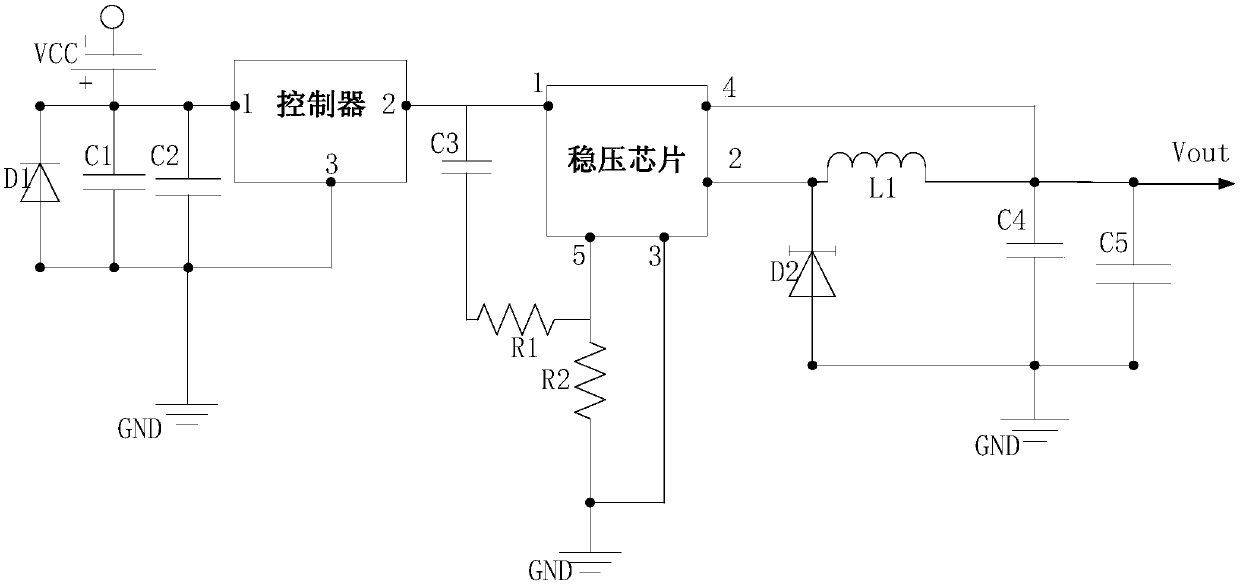
[0019] Such as figure 1 as shown, figure 1 It is a schematic structural diagram of a switching power supply circuit provided by an embodiment of the present invention. The embodiment of the present invention provides a switching power supply circuit based on an STM32 microprocessor, including a controller and a voltage stabilizing chip, the power supply is connected to the voltage stabilizing chip through the controller,
[0020] The first pin of the controller is connected to the power supply, the second pin of the controller is connected to the first pin of the voltage regulator chip, and the third pin of the controller is grounded;
[0021] The second pin of the voltage stabilizing chip is connected to the communication bus, and a feedback inductor L1 is arranged on the communication bus; the fourth pin of the voltage stabilizing chip is connected to the feedback inductor L1, and is connected in series with the second pin of the voltage stabilizing chip to form a feedback ...
Embodiment 2
[0039] On the basis of the above-mentioned embodiments, this embodiment describes various parameters in the switching power supply circuit in detail.
[0040] First, the input voltage of the power supply terminal is 12V, and the voltage regulator chip is LM2596 chip.
[0041] The first capacitor C1 is an electrolytic capacitor with a voltage of 100 microfarads and a withstand voltage of 35V, which is an energy storage capacitor; the second capacitor C2 is an ordinary capacitor with a value of 0.1 microfarads; the first capacitor C1 and the second capacitor C2 are connected in parallel to the incoming line of the power supply filtering.
[0042] The third capacitor C3 is 0.1 microfarads, the first resistor R1 is 47 kohms, and the second resistor R2 is 47 kohms. The three are connected in series between the power supply terminal and the ground terminal, and connected to the fifth pin of the voltage regulator chip ( Enable end) connected to form a delay start circuit, used to pr...
Embodiment 3
[0048] On the basis of above-mentioned embodiment one and embodiment two, this embodiment is specifically as follows:
[0049] The first resistor R1 is a variable resistor, and the resistance value of the first resistor R1 is controlled by an FPGA module.
[0050] Specifically, the first resistor R1 plays the role of consuming voltage and reducing the voltage in the switching power supply circuit. By adjusting the resistance value of the first resistor R1, the output terminal of the voltage stabilizing chip can output voltages of different sizes. Therefore, this In the embodiment, the first resistor R1 is a variable resistor, and its resistance can be adjusted according to different types of requirements. Specifically, by setting the FPGA module, the resistance value of the variable resistor can be adjusted by using the programmability of the FPGA module. In this way, The resistance variation range of the first resistor R1 is no longer limited by the internal circuit of the vo...
PUM
| Property | Measurement | Unit |
|---|---|---|
| Third capacitor | aaaaa | aaaaa |
Abstract
Description
Claims
Application Information
 - R&D
- Intellectual Property
- Life Sciences
- Materials
- Tech Scout
- Unparalleled Data Quality
- Higher Quality Content
- 60% Fewer Hallucinations
Browse by: Latest US Patents, China's latest patents, Technical Efficacy Thesaurus, Application Domain, Technology Topic, Popular Technical Reports.
© 2025 PatSnap. All rights reserved.Legal|Privacy policy|Modern Slavery Act Transparency Statement|Sitemap|About US| Contact US: help@patsnap.com