Chirp spread spectrum modulation and demodulation method and system based on QPSK

A spread spectrum modulation and demodulation, modulated signal technology, applied in the modulation carrier system, multi-frequency code system, phase modulation carrier system and other directions, can solve the problem of increasing the complexity of the receiving system, long synchronization time for weak signals, and complicated GPS receiver design. and other problems, to achieve the effect that the demodulation algorithm is simple, easy to implement, easy to handle, and simple in method.

Active Publication Date: 2020-05-19
BEIJING SENSORO
View PDF4 Cites 9 Cited by
  • Summary
  • Abstract
  • Description
  • Claims
  • Application Information

AI Technical Summary

Problems solved by technology

However, the design of the GPS receiver is quite complicated, and the synchronization time for weak signals is very long
The communication system modulated by digitally synthesized chirp symbols used by LoRa transceivers has also reached a high ...

Method used


Image

  • Chirp spread spectrum modulation and demodulation method and system based on QPSK
  • Chirp spread spectrum modulation and demodulation method and system based on QPSK
  • Chirp spread spectrum modulation and demodulation method and system based on QPSK

Examples


Embodiment 1

[0038] A chirp spread spectrum modulation and demodulation method based on QPSK, is characterized in that, described method comprises the steps:

[0039] S1. Generate a fixed-length chirp signal according to parameter configuration, and the chirp signal includes an upchirp signal and a downchirp signal;

[0040] S2. Combining the chirp signal into a frame header signal;

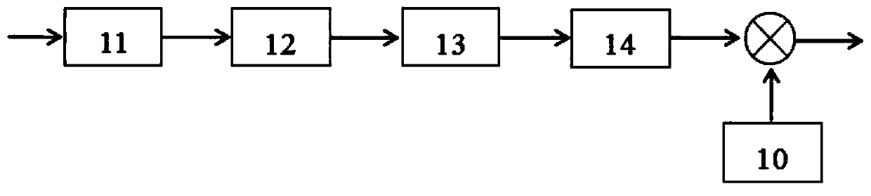
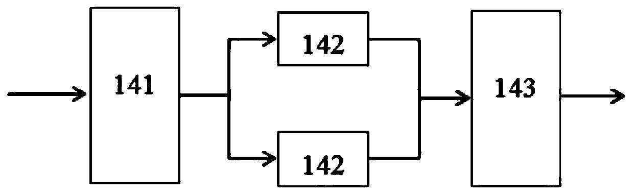
[0041] S3. Convert the original transmission signal to be transmitted into a QPSK signal, and then multiply the QPSK signal by the upchirp signal to generate a modulated signal.

[0042] S4. Combining the frame header signal and the modulated signal to generate complete data information; modulating the data information into a radio frequency signal through a radio frequency transmission module and transmitting it;

[0043] S5. The radio frequency receiving module of the receiving link converts the radio frequency data into baseband data;

[0044]S6. Perform symbol synchronization on the baseband signal, and...

Embodiment 2

[0055] A chirp spread spectrum modulation and demodulation system based on QPSK, for realizing the method in embodiment 1, described modulation and demodulation system comprises radio frequency module, baseband modulation module and baseband demodulation module; Described radio frequency module comprises radio frequency transmission module And radio frequency receiving module; Described baseband modulation module comprises chirp generator, frame header generation module, data modulation module and frame composition module; Described baseband demodulation module comprises synchronization module, time-frequency correction module, QPSK demodulation module, deinterleaving module, de-whitening module and decoding module;

[0056] The chirp generator is used to generate a fixed-length chirp signal according to parameter configuration, and the frame header generating module is used to combine the chirp signal generated by the chirp generator into a frame header signal according to a c...


PUM


Abstract

The invention relates to a chirp spread spectrum modulation and demodulation method based on QPSK (Quadrature Phase Shift Keying). The method comprises the following steps: S1, generating a chirp signal with a fixed length according to parameter configuration; S2, combining the chirp signal into a frame header signal according to a certain format; S3, converting an original sending signal to be sent into a QPSK signal, and then multiplying the QPSK signal by an upchirp signal to generate a modulation signal; S4, combining the frame header signal with the modulation signal to generate completedata information, and transmitting the data information through the radio frequency transmitting module; S5, converting the data information into a baseband signal; S6, converting the baseband into adispreading signal; S7, converting a despread signal into demodulation data; S8, de-interleaving, de-whitening and decoding the demodulated data, and recovering the demodulated data into an original sending signal. The demodulation algorithm is simple and easy to implement, and signal synchronization is easy to process.

Description

technical field [0001] The invention relates to the technical field of wireless communication, in particular to a method and system for QPSK-based chirp spread spectrum modulation and demodulation. Background technique [0002] At present, wireless communication has been developing rapidly all over the world, and has become a hot technology of common concern in the global communication and IT circles. Especially with the comprehensive development of the Internet of Things in the world, not only the basic technology of wireless communication has been continuously improved, developed and changed, Furthermore, various types of wireless communication systems and new wireless communication technologies emerge continuously, and the market demand for wireless communication technology also grows rapidly. Long-distance transmission, low complexity, and low power consumption have become the pursuit of wireless communication chips for the Internet of Things industry in the new era. Th...

Claims


Application Information

Patent Timeline
IPC IPC(8): H04B1/7073H04L1/00H04L27/00H04L27/20H04L27/227H04L27/26
CPCH04B1/7073H04L27/2662H04L27/20H04L27/2278H04L27/0014H04L1/0071H04L1/0061H04L2027/0026
Inventor 熊艳伟郑波浪李晓明李建龙刘伟
Owner BEIJING SENSORO
Why Eureka
Try Eureka