

Airflow sensor, breathing mask equipped with same, and tidal volume measuring method
A technology of airflow sensor and respiratory mask, applied in the field of respiratory mask and tidal volume measurement, can solve the problems of obstructing human movement, troublesome wearing, and large air output, so as to reduce the probability of poisoning, facilitate human movement, and reduce the wearing length. Effect
- Summary
- Abstract
- Description
- Claims
- Application Information
AI Technical Summary
Problems solved by technology
Method used
Image


Examples
Embodiment 1
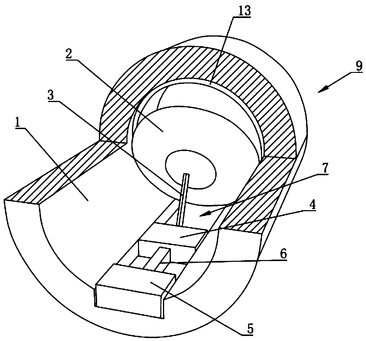
[0033] Such as Figure 1-3 As shown, an airflow sensor includes a housing 1, a flap 2, a support rod 3, a sliding block 4, a pressure sensor 5 with a wireless communication function and a stretchable pressure transmission strip 6, and the housing 1 is connected at both ends Cylindrical housing structure, the inner wall of the housing 1 is provided with a chute 7, the pressure sensor 5 is arranged at one end of the chute 7, and one side of the sliding block 4 passes through the pressure transmission bar 6 Connected to the detection end of the pressure sensor 5, the sliding block 4 is matched with the chute 7 and slidably arranged in the chute 7, and the side of the sliding block 4 away from the pressure sensor 5 is supported by The rod 3 is connected to the blocking piece 2, one end of the supporting rod 3 is hinged to the blocking piece 2, the other end of the supporting rod 3 is fixedly connected to the sliding block 4, and the blocking piece 2 is connected to the inner diame...
Embodiment 2
[0041] Such as Figure 1-4 As shown, this embodiment is a breathing mask with an airflow sensor in Embodiment 1, including a breathing mask body 8, a connection hole is provided at the front center of the breathing mask body 8, and the airflow sensor 9 is connected to the airflow sensor through the connection hole. The airflow sensor 9 is connected to the main body 8 of the breathing mask, and one end of the flap 2 of the airflow sensor 9 is arranged close to the main body 8 of the breathing mask. The two sides of the connection hole are respectively symmetrically provided with one-way valves 10 for inhalation. The valve 10 communicates with the mask body.
[0042] During use, the respiratory mask body 8 is worn and starts to breathe normally. Due to the existence of the retaining ring 13 during inhalation, the restriction flap is opened during inhalation, and the air can only be fed through the one-way valve 10. The pressure is too high, so the one-way valve 10 is closed and...
Embodiment 3
[0046] The present embodiment is a method for measuring tidal volume based on the breathing mask in Embodiment 2, comprising the following steps:
[0047] S10: Wear a breathing mask; breathe through the breathing mask;
[0048] S20: Open the flap 2; the exhaled gas acts on the flap 2, and the flap 2 rotates under pressure;
[0049] S30: push the sliding block 4; during the rotating process of the blocking plate 2, the sliding movement is driven by the support rod 3 towards the direction of the pressure sensor 5;
[0050] S40: pressure transmission; the sliding block 4 squeezes the pressure transmission bar 6 during the movement process, and the pressure transmission bar 6 transmits the pressure signal to the pressure sensor 5;
[0051] S50: signal transmission; the pressure sensor 5 transmits the pressure signal to the computer through wireless communication;
[0052] S60: Calculate the tidal volume; the computer calculates the tidal volume according to the pressure signal t...
PUM
 Abstract
Description
Claims
Application Information