
Hot runner system applied to heat-sensitive injection molding material, and application method of hot runner system

A hot runner, heat-sensitive technology, applied in the field of injection molds, can solve the problems of reduced installation and use quality, hindered plastic flow, scorching, etc., to avoid stress shearing and resistance, and avoid scorching.

Pending Publication Date: 2020-05-22
亿美特装备(武汉)有限公司
View PDF0 Cites 0 Cited by
  • Summary
  • Abstract
  • Description
  • Claims
  • Application Information

AI Technical Summary

Problems solved by technology

[0002] When heat-sensitive materials are scorched, carbonized, or yellowed, the conventional hot runner system can only be melted by other cleaning materials, and then use its flushing and melt viscosity to remove the burnt heat-sensitive residue from the inner wall of the manifold flow channel. Peel it off, and finally extrude the hot nozzle through injection glue. The entire cleaning process usually takes more than 10 hours, and usually when the heat-sensitive material is carbonized and scorched seriously, its corrosion is very strong, and the flow of the splitter plate There will also be a certain degree of corrosion on the inner wall of the tunnel, and then local material changes and damages will occur. This part of the abnormal materials will occasionally peel off irregularly and be mixed into the post-melted plastic; and these metal residues cannot be covered by cleaning materials. One of the results is that the injection hole of the hot nozzle will be blocked later and the hot runner system will be damaged.
[0003] Secondly, due to the characteristics of temperature sensitivity and temperature control instability of heat-sensitive materials, the conventional hot runner system can only reach the state of being meltable and can be injected and extruded, but it is difficult to guarantee its long-term stable state, especially in the When heat-sensitive materials are burnt, carbonized, and yellowed, the conventional hot runner structure cannot quickly and completely remove the waste (due to the overall production of the conventional hot runner manifold, it cannot be disassembled); another result is long-term shutdown , Remove and replace the barrel screw, polish and polish, then reinstall, debug and reproduce; and such processes or conditions will occur frequently, seriously restricting production efficiency and benefits
[0004] In addition, in the current conventional hot runner, the processing of the plastic flow channel in the manifold is limited to the characteristics of the processing machine (that is, the drilling machine). It can only be drilled in and out of a straight line, and the part where the vectors intersect cannot be processed into an arc. The curved surface can only be processed into acute and sharp corners, and the problems presented by such processing results are: 1) During injection molding, there are stress shear and resistance to the melt at the corner of the channel in the manifold, which seriously hinders The flow of plastic leads to the accumulation of plastic and increases the injection pressure; 2) After a long time, the collection area will be heated for a long time to cause problems such as burning and blackening, which will affect the speed and efficiency of the hot runner, and even cause black spots on the product , affecting product quality
When this happens, it is usually necessary to regularly clean and clear the hot runner path to ensure the normal operation of the hot runner, but this will lead to frequent shutdowns and starts of the operating machine, greatly reducing production efficiency; Unreasonable production and frequent disassembly, cleaning, cleaning, resulting in the reduction of installation and use quality

Method used


Image

  • Hot runner system applied to heat-sensitive injection molding material, and application method of hot runner system
  • Hot runner system applied to heat-sensitive injection molding material, and application method of hot runner system
  • Hot runner system applied to heat-sensitive injection molding material, and application method of hot runner system

Examples


Embodiment Construction

[0067] In order to make the technical means, creative features, goals and effects achieved by the present invention easy to understand, the following will further explain how the present invention is implemented in conjunction with the accompanying drawings and specific implementation methods.

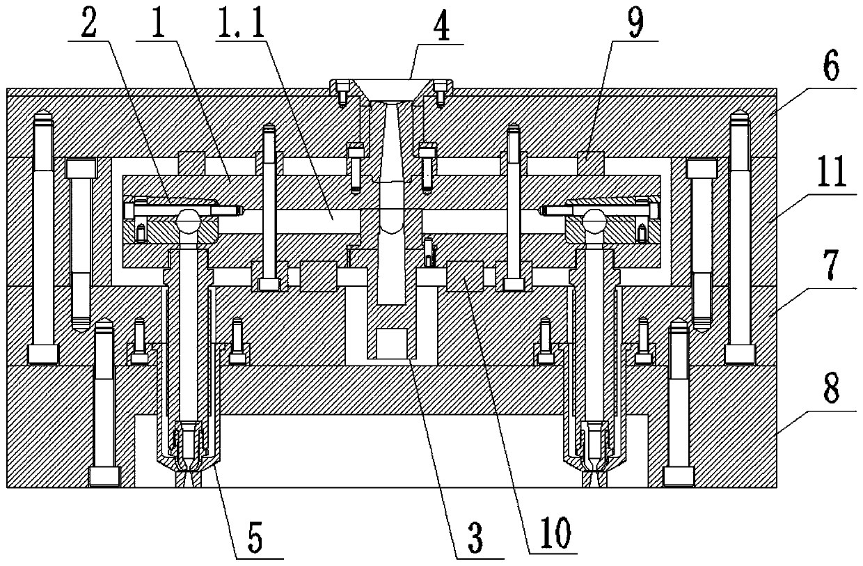
[0068] refer to figure 1 As shown, the present invention provides a hot runner system for heat-sensitive injection molding materials, including a manifold 1, a runner rotary cutter 3, a main injection nozzle 4, several inserts 2, and several sub-injection nozzles 5;

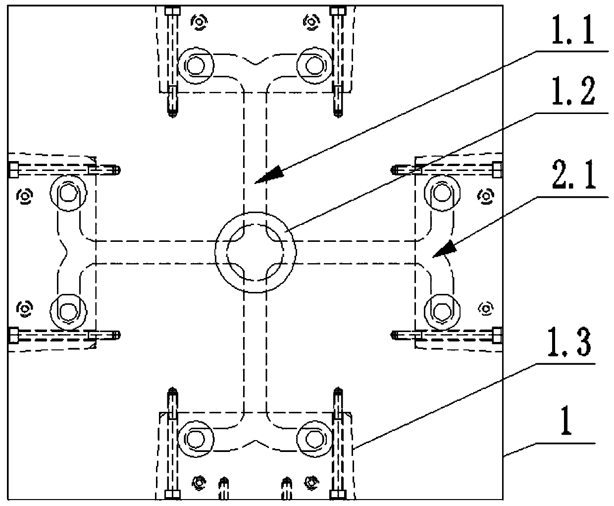
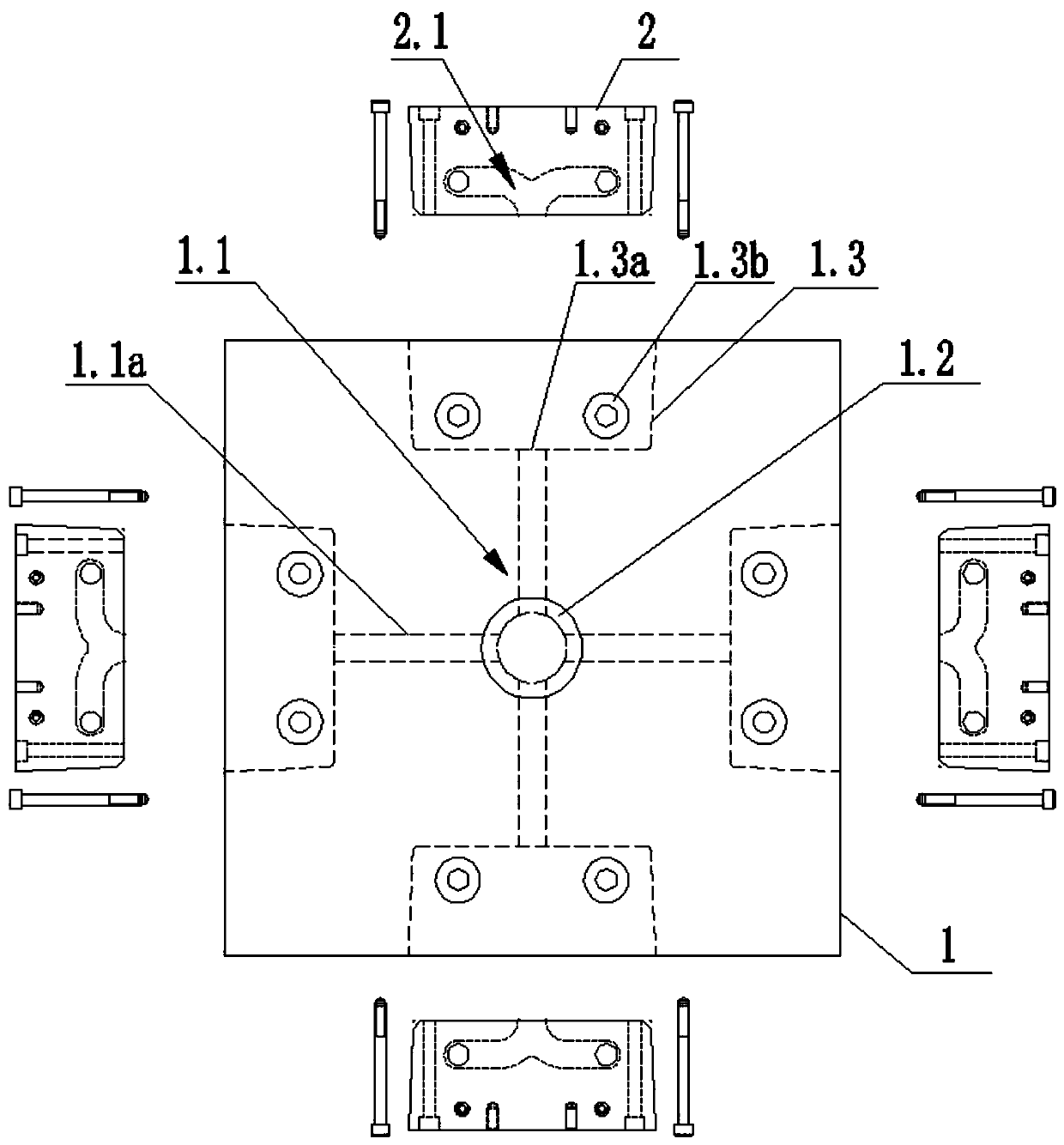
[0069] Specifically, see Figure 1 to Figure 6As shown, a first distribution channel 1.1 is provided inside the distribution plate 1, and a cutter groove 1.2 is provided at the bottom of the distribution plate 1 and at the vector intersection of the first distribution channel 1.1. An insert groove 1.3 is installed in the cutter groove 1.2, and a runner rotary cutter 3 corresponding to the rotary cutting corresponding to...


PUM


Abstract

The invention discloses a hot runner system applied to a heat-sensitive injection molding material, and an application method of the hot runner system. The hot runner system comprises a splitter plate; the splitter plate is internally provided with first splitter passages; the part, positioned at a vector intersection position of the first splitter passages, of the bottom of the splitter plate isprovided with a cutting knife groove; the circumferential side of the splitter plate is provided with a plurality of insert grooves; a runner rotating cutting knife which is matched with the vector intersection position of the first splitter passages and corresponds to the vector intersection position of the first splitter passages in a rotary cutting manner is installed inside the cutting knife groove; each insert groove is internally and detachably provided with one insert in an embedding manner; each insert is internally provided with a second splitter passage; each first splitter passage correspondingly communicates with the cutting knife groove and the second splitter passage which is arranged inside the corresponding insert; and the application method of the hot runner system comprises an installation method for the hot runner system and a method for clearing residual materials inside a runner of the hot runner system. The hot runner system disclosed by the invention has the advantages of being convenient to process and manufacture, convenient to mount and dismount, realizing convenient, complete and clean clearing of the residual materials and the like.

Description

technical field [0001] The invention relates to a hot runner system, which belongs to the technical field of injection molds, in particular to a hot runner system for heat-sensitive injection molding materials and a method for using it. Background technique [0002] When heat-sensitive materials are scorched, carbonized, or yellowed, the conventional hot runner system can only be melted by other cleaning materials, and then use its flushing and melt viscosity to remove the burnt heat-sensitive residue from the inner wall of the manifold flow channel. Peel it off, and finally extrude the hot nozzle through injection glue. The entire cleaning process usually takes more than 10 hours, and usually when the heat-sensitive material is carbonized and scorched seriously, its corrosion is very strong, and the flow of the splitter plate There will also be a certain degree of corrosion on the inner wall of the tunnel, and then local material changes and damages will occur. This part of...

Claims


Application Information

Patent Timeline
Patent Type & Authority Applications(China)
IPC IPC(8): B29C45/27B29C45/26B29C45/38B29C33/30
CPCB29C33/305B29C45/2602B29C45/27B29C45/38B29C2045/2759B29C2045/384
Inventor 程学南徐冲
Owner 亿美特装备(武汉)有限公司
Learn More