
Curvature compensation low-temperature drift band-gap reference voltage source circuit

A reference voltage source and curvature compensation technology, which is applied in the direction of adjusting electrical variables, control/regulation systems, instruments, etc., can solve the problems of increased output voltage temperature drift coefficient, low circuit accuracy, and numerical deviation, etc., to achieve the reduction of temperature drift coefficient , Reduce the impact of operational amplifier input offset voltage and noise, low noise effect

Active Publication Date: 2020-05-22
TSINGHUA UNIV
View PDF5 Cites 16 Cited by
  • Summary
  • Abstract
  • Description
  • Claims
  • Application Information

AI Technical Summary

Problems solved by technology

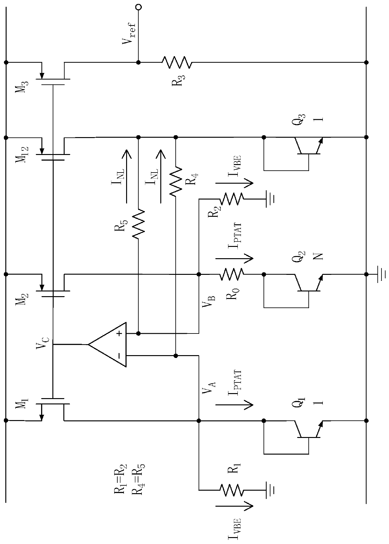
[0005] However, this circuit has the following disadvantages: 1. In the bandgap reference core circuit, the mismatch between the input transistors of the op amp will cause the input offset voltage of the op amp, resulting in V A , V B The voltages at two points are not exactly equal, and this offset voltage, after a certain proportional gain, will affect V ref The value of V has a certain influence, causing V ref The voltage is greatly discrete due to the influence of the process and the environment, so the accuracy of the circuit is low
In addition, the noise of the op amp will also affect the output voltage V ref 2. The offset voltage of the op amp generally has a certain drift coefficient with temperature, and this drift coefficient will affect V ref Produce a certain influence, so that the temperature drift coefficient of the output voltage increases

Method used


Image

  • Curvature compensation low-temperature drift band-gap reference voltage source circuit
  • Curvature compensation low-temperature drift band-gap reference voltage source circuit
  • Curvature compensation low-temperature drift band-gap reference voltage source circuit

Examples


Embodiment Construction

[0035] The technical solutions in the embodiments of the present invention will be clearly and completely described below in conjunction with the accompanying drawings in the embodiments of the present invention. Obviously, the described embodiments are part of the embodiments of the present invention, but not all of them. Based on the implementation manners in the present invention, all other implementation manners obtained by persons of ordinary skill in the art without making creative efforts belong to the scope of protection of the present invention.

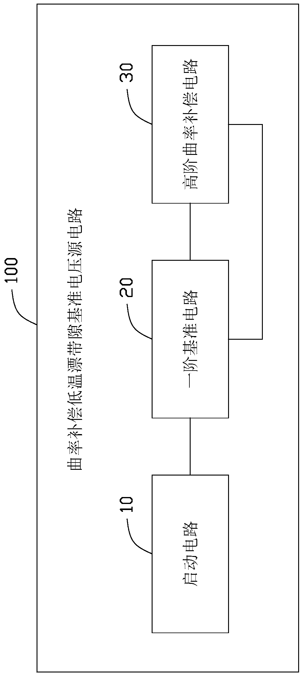
[0036] see figure 2 , an embodiment of the present application provides a curvature compensation low temperature drift bandgap reference voltage source circuit 100 .

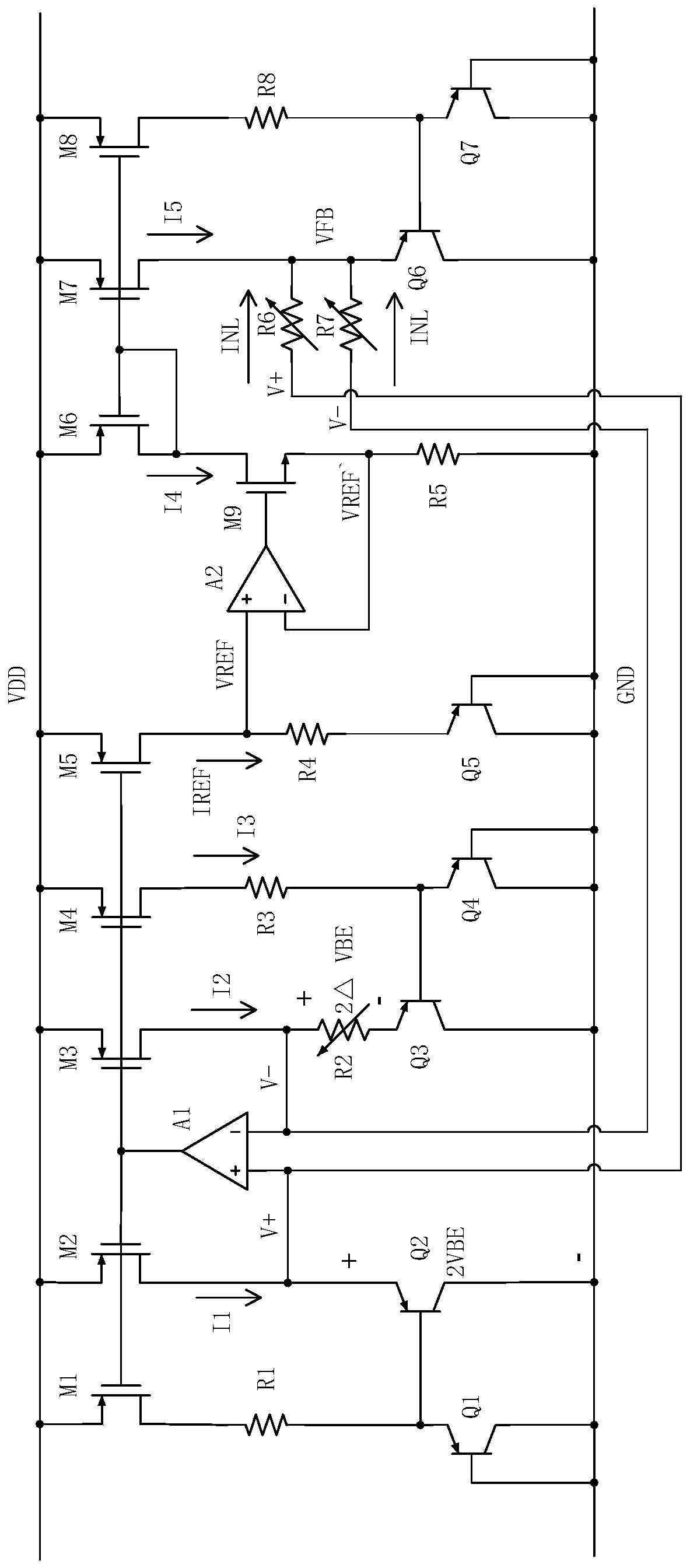
[0037] The curvature compensation low-temperature drift bandgap reference voltage source circuit 100 is used to generate a reference voltage, and the curvature compensation low-temperature drift bandgap reference voltage source circuit 100 may include a start...


PUM


Abstract

The embodiment of the invention provides a curvature compensation low-temperature drift band-gap reference voltage source circuit. The curvature compensation low-temperature drift band-gap reference voltage source circuit is used for generating a reference voltage, and comprises a starting circuit, a first-order reference circuit and a high-order curvature compensation circuit; the starting circuit is used for providing starting voltage for a voltage reference source circuit so as to prevent the voltage reference source circuit from working in a zero state region, the first-order reference circuit is used for generating low-temperature coefficient reference voltage, and the high-order curvature compensation circuit is used for performing high-order temperature curvature compensation on thefirst-order reference circuit. According to the technical scheme, influence of input offset voltage and noise of an operational amplifier is effectively reduced in a multi-stage PNP superposition mode, and meanwhile, a high-order curvature compensation method is provided for the multi-stage PNP superposition band-gap reference source circuit, so that the temperature drift coefficient of the band-gap reference source is effectively reduced.

Description

technical field [0001] The present application relates to a reference voltage source circuit, in particular to a curvature compensation low-temperature drift bandgap reference voltage source circuit. Background technique [0002] With the continuous advancement of integrated circuit technology, bandgap reference sources are more and more widely used in various electronic systems, such as temperature sensors, power regulators, digital-to-analog converters, analog-to-digital converters, and memory circuits. With the continuous upgrading of technology, the system's requirements for various performance indicators of the bandgap reference are also increasing. The bandgap reference provides a reference voltage for the entire system, and its performance will directly affect the performance of the entire system. Therefore, the output reference voltage is required to have a lower temperature coefficient and higher precision, that is, the circuit distribution range is relatively smal...

Claims


Application Information

Patent Timeline
IPC IPC(8): G05F1/567
CPCG05F1/567
Inventor 李福乐周喆
Owner TSINGHUA UNIV
Learn More