
A Simple Electromagnetic Force Wiring Device

A wiring device, electromagnetic force technology, applied in the direction of conductive connection, electrical component connection, connection, etc., can solve problems such as poor contact, and achieve the effect of improving work efficiency, strong on-site practicability, and flexible and convenient fixing or removal of wiring.

Active Publication Date: 2021-04-02
STATE GRID HENAN ELECTRIC POWER ELECTRIC POWER SCI RES INST +1
View PDF1 Cites 0 Cited by
  • Summary
  • Abstract
  • Description
  • Claims
  • Application Information

AI Technical Summary

Problems solved by technology

[0005] The technical problem to be solved by the present invention is: in order to solve the problem of poor contact between large and small wire clamps or terminal blocks and electric equipment in the prior art, thereby providing a simple and convenient electromagnetic force connection device with good effect

Method used


Image

  • A Simple Electromagnetic Force Wiring Device

Examples


Embodiment Construction

[0020] It should be noted that, in the case of no conflict, the embodiments in the present application and the features in the embodiments can be combined with each other.

[0021] In the description of the present application, it should be understood that the terms "center", "longitudinal", "transverse", "upper", "lower", "front", "rear", "left", "right", " The orientation or positional relationship indicated by "vertical", "horizontal", "top", "bottom", "inner", "outer", etc. is based on the orientation or positional relationship shown in the drawings, and is only for the convenience of describing the present application and Simplified descriptions do not indicate or imply that the device or element referred to must have a specific orientation, be constructed and operate in a specific orientation, and thus should not be construed as limiting the scope of protection of the present application. In addition, the terms "first", "second", etc. are used for descriptive purposes on...


PUM


Abstract

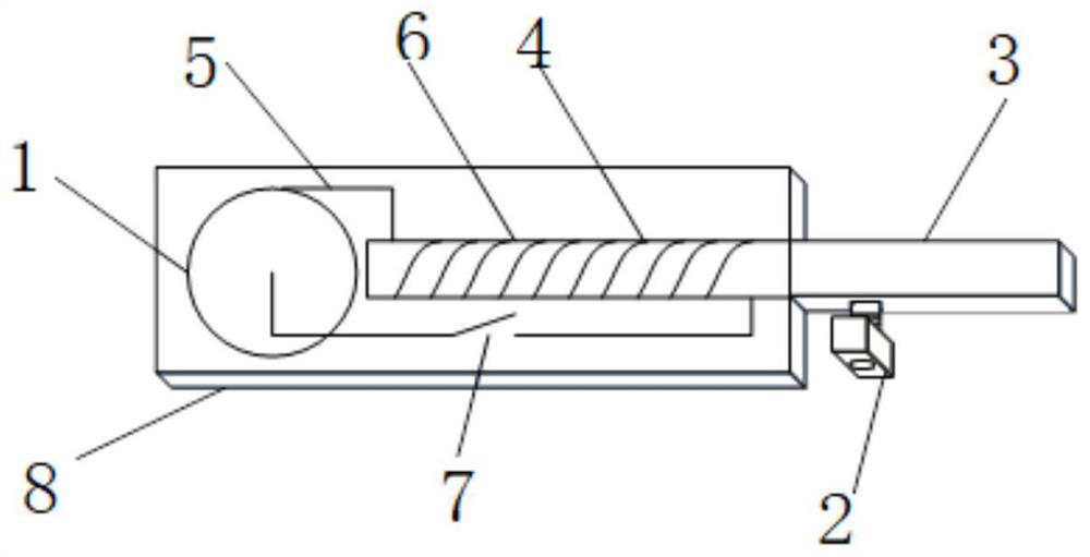
The invention relates to a simple electromagnetic force wiring device. The simple electromagnetic force wiring device is characterized in that the simple electromagnetic force wiring device comprisescomprises a power supply, an electromagnetic generation assembly and a wiring assembly, the electromagnetic generation assembly is separately connected with the power supply and the wiring assembly, the wiring assembly comprises a metal binding post used for being externally connected with a metal wire and a wiring terminal making contact with grounding flat iron of power equipment, the metal binding post is connected to the wiring terminal, and the power supply current passes through the electromagnetic generation assembly and generates magnetic attraction force on the wiring terminal. The simple electromagnetic force wiring device has the beneficial effects that the wiring terminal generates magnetism through the magnetic force capable of being switched on and off, tight contact (approximate face-to-face contact) between the wiring terminal and a contact point is achieved, meanwhile, wiring is very flexible and convenient to fix or detach, the working efficiency is greatly improved,and the field practicability is very high.

Description

technical field [0001] The application belongs to the technical field of electric devices, and in particular relates to a simple electromagnetic force connection device. Background technique [0002] In the electric power field electrical test, it is usually necessary to use various size clamps or terminal blocks for current and voltage signal wiring or grounding. At present, most of the wire clips used in wiring are crocodile clips, cylindrical terminal blocks or fork wires, which are clamped or inserted on the surface of the flat iron or grounded flat iron of the electric equipment only by its mechanical force, and the current flow is tested. It all depends on the quality of the contact (point-to-point contact) between the terminal block and the flat iron. [0003] For tests that are sensitive to the test current, the quality of the contact resistance between the clamp and the flat iron will directly affect the quality of the test data. After the first use, there are sti...

Claims


Application Information

Patent Timeline
Patent Type & Authority Patents(China)
IPC IPC(8): H01R11/30
CPCH01R11/30
Inventor 郭磊寇晓适张科董曼玲丁国君刘阳陶亚光
Owner STATE GRID HENAN ELECTRIC POWER ELECTRIC POWER SCI RES INST
Learn More