
Full-automatic welding device for welding metal strip on side part of metal plate and using method of full-automatic welding device

A fully automatic welding and metal sheet technology, applied in welding equipment, auxiliary devices, welding equipment, etc., can solve the problems of high labor welding cost, uneven welding seam, complicated welding process, etc., saving labor cost and huge economic benefits , The effect of low configuration cost

Pending Publication Date: 2020-05-26
ANHUI ZHONGLIANLYVJIAN STEEL STRUCTURE TECH CO LTD
View PDF0 Cites 0 Cited by
  • Summary
  • Abstract
  • Description
  • Claims
  • Application Information

AI Technical Summary

Problems solved by technology

[0002] Nowadays, welding work is very common in various industries. Most of the welding equipment has not yet achieved full-automatic welding, and most of them are still manual welding, which is highly dependent on manual welding. The welding process is complicated; the effect of manual welding is also very poor in terms of welding effect, and the weld seam often welded is uneven, inconsistent, and unsightly; the cost of manual welding is relatively high, and it cannot be mass-produced, so it is not suitable for assembly line production , unable to bring greater economic benefits to the enterprise

Method used


Image

  • Full-automatic welding device for welding metal strip on side part of metal plate and using method of full-automatic welding device
  • Full-automatic welding device for welding metal strip on side part of metal plate and using method of full-automatic welding device
  • Full-automatic welding device for welding metal strip on side part of metal plate and using method of full-automatic welding device

Examples


Embodiment Construction

[0022] Referring to the accompanying drawings, through the description of the embodiments, the specific implementation of the present invention, such as the shape, structure, mutual position and connection relationship between the various parts, the function and working principle of each part, and the manufacturing process And the method of operation and use, etc., are described in further detail to help those skilled in the art have a more complete, accurate and in-depth understanding of the inventive concept and technical solution of the present invention.

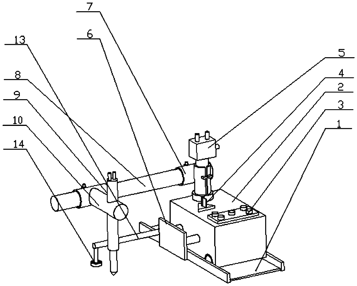
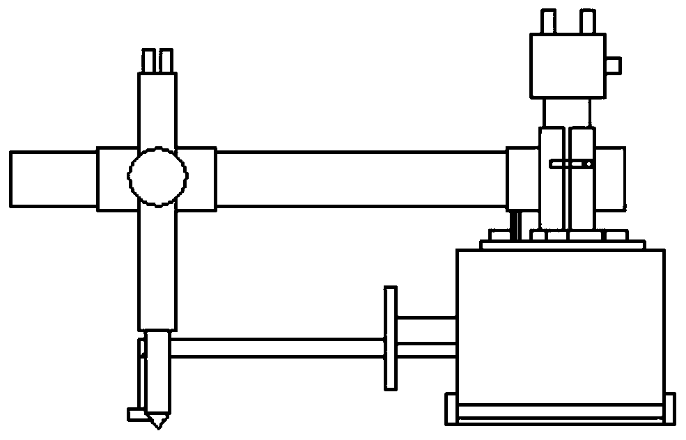
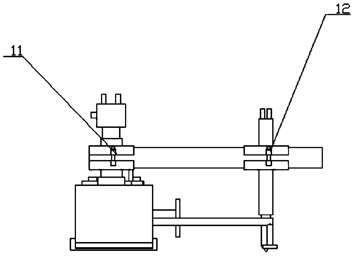
[0023] figure 1 is an axonometric view of the present invention, figure 2 It is the front view of the present invention, image 3 It is the rear view of the present invention; as figure 1 , figure 2 with image 3 A fully automatic welding device for welding metal strips on the side of metal plates, including a track 1 and a submerged arc welding vehicle 2 arranged on the track 1. A control panel 3 is provided at on...


PUM


Abstract

The invention discloses a full-automatic welding device for welding a metal strip on the side part of a metal plate. The device comprises a rail and a submerged-arc welding vehicle arranged on the rail, and is characterized in that a control panel is arranged at one end of the roof of the welding vehicle, a longitudinal first clamp body is arranged at the other end, far away from the control panel, of the roof of the welding vehicle, the control panel and the first clamp body are fixedly connected with the roof, the side part of the first clamp body is fixedly connected with a second clamp body which is transversely arranged, and the first clamp body is fixedly connected with the second clamp body. By the adoption of the scheme, the full-automatic welding process that the metal strip is welded on the side part of the metal plate can be achieved, manual welding is not needed, the labor cost of an enterprise is saved, the welding vehicle runs at a constant speed so that uniformity of weld joints can be guaranteed, the weld joints are attractive, the structure is simple, and the configuration cost of the device is low; and a plurality of devices can work simultaneously, large-batch production of enterprise production and manufacturing is carried out, assembly line work is carried out, and huge economic benefits are brought to the enterprise.

Description

technical field [0001] The invention belongs to the field of welding, and more specifically, the invention relates to a fully automatic welding device for welding metal strips at the side of metal plates and a method for using the same. Background technique [0002] Nowadays, welding work is very common in various industries. Most of the welding equipment has not yet achieved full-automatic welding, and most of them are still manual welding, which is highly dependent on manual welding. The welding process is complicated; the effect of manual welding is also very poor in terms of welding effect, and the weld seam often welded is uneven, inconsistent, and unsightly; the cost of manual welding is relatively high, and it cannot be mass-produced, so it is not suitable for assembly line production , unable to bring greater economic benefits to the enterprise. Contents of the invention [0003] The technical problem to be solved by the present invention is to provide a full-auto...

Claims


Application Information

Patent Timeline
Patent Type & Authority Applications(China)
IPC IPC(8): B23K9/32B23K9/18B23K37/02
CPCB23K9/32B23K9/18B23K37/02B23K37/0211
Inventor 张伟王大权
Owner ANHUI ZHONGLIANLYVJIAN STEEL STRUCTURE TECH CO LTD
Learn More