
Thermal cycle energy-saving injection molding machine

An injection molding machine and thermal cycle technology, applied in the field of polymer material molding machinery, can solve problems such as energy consumption, achieve the effect of improving heating efficiency and realizing energy cycle

Pending Publication Date: 2020-05-26
TEDERIC MACHINERY
View PDF1 Cites 2 Cited by
  • Summary
  • Abstract
  • Description
  • Claims
  • Application Information

AI Technical Summary

Problems solved by technology

[0007] The purpose of the present invention is to provide a thermal cycle energy-saving injection molding machine. Aiming at the defect that both plasticization and cooling of the existing injection molding machine consume energy, a thermal cycle solution is proposed

Method used


Image

  • Thermal cycle energy-saving injection molding machine
  • Thermal cycle energy-saving injection molding machine
  • Thermal cycle energy-saving injection molding machine

Examples


Embodiment Construction

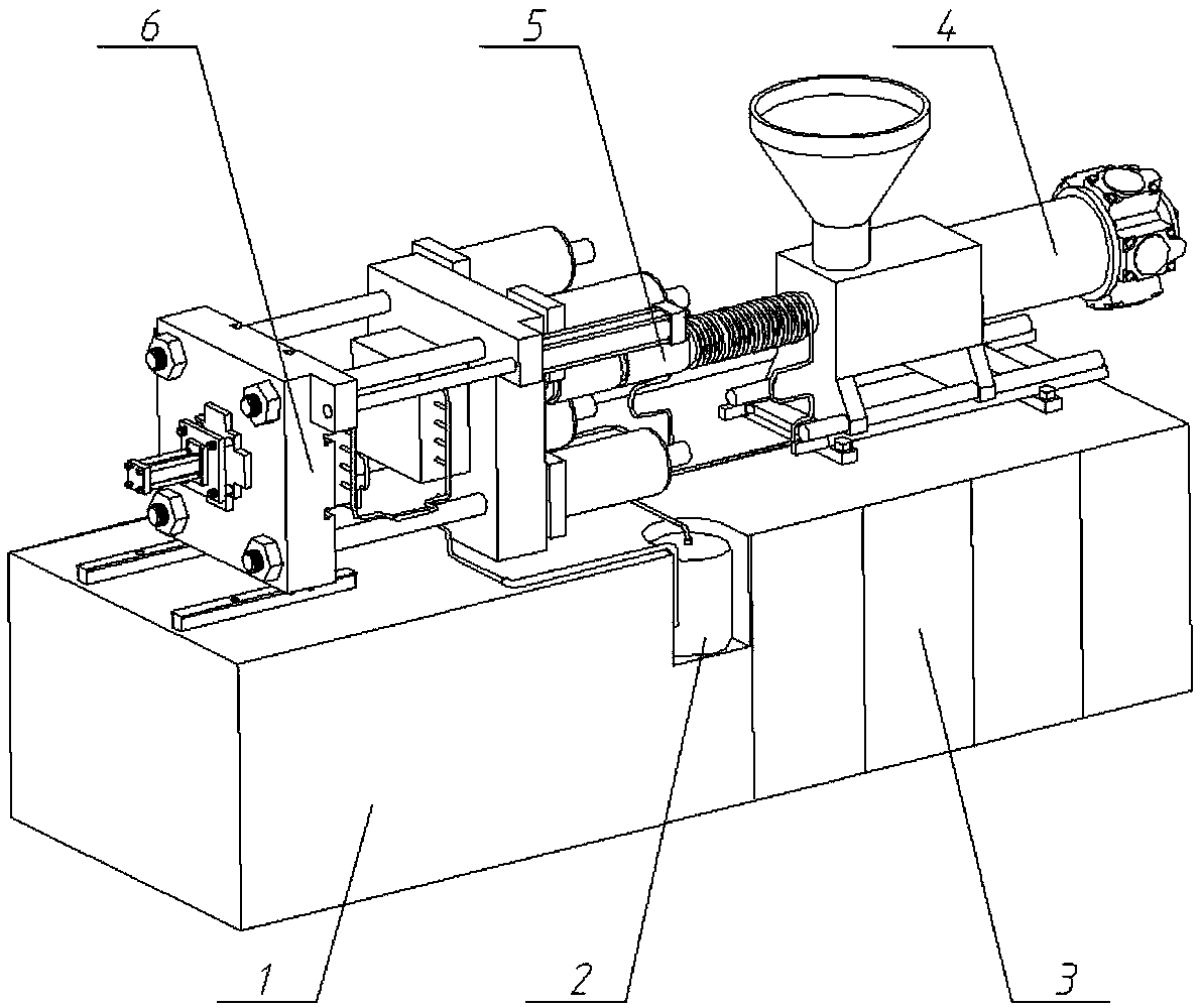
[0024] The object of the present invention is to provide a thermal cycle energy-saving injection molding machine such as figure 1 As shown, it is mainly composed of frame 1, thermal cycle system 2, control system 3, injection system 4, plasticizing system 5, mold clamping system 6 and so on. Except for the thermal cycle system 2, other devices are the same as the traditional injection molding machine.

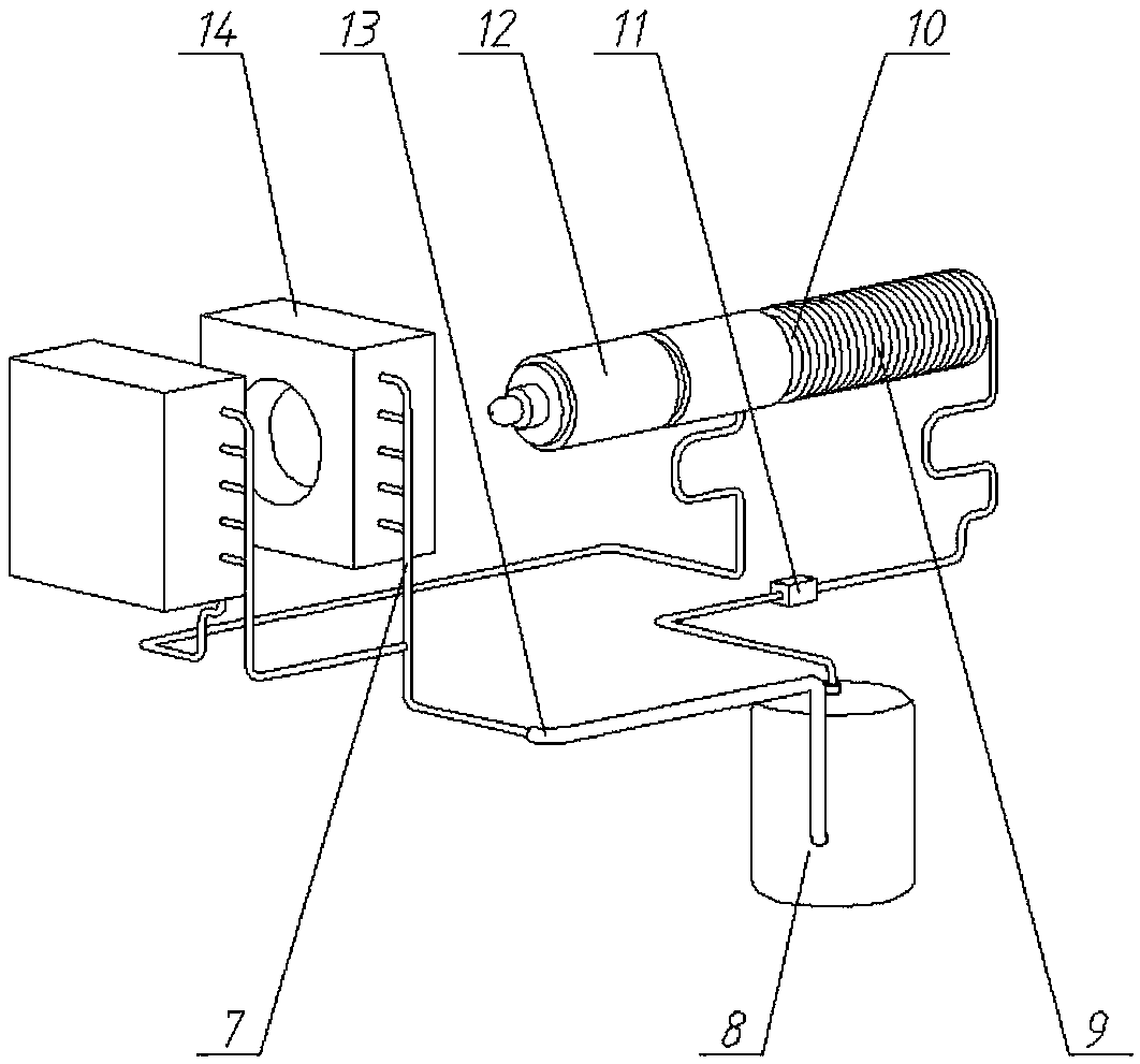
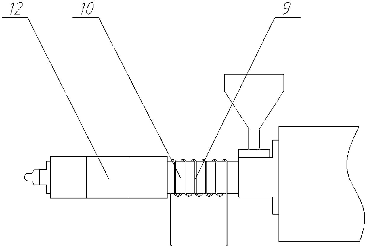
[0025] The thermal cycle system 2 is mainly composed of an evaporator 7, a compressor 8, a condenser 9, a barrel 10, an expansion valve 11, a heating coil 12, a connecting pipe 13, and a refrigerant, etc., such as figure 2 shown. The evaporator 7 is arranged in the mold 14, the compressor 8 is arranged at the lower body between the front template of the injection molding machine and the injection seat, and the condenser 9 is arranged on the cylinder 10, as image 3 As shown, the expansion valve 11 is arranged between the compressor 8 and the condenser 9, and the connecting p...


PUM


Abstract

The invention discloses a thermal cycle energy-saving injection molding machine. The thermal cycle energy-saving injection molding machine mainly comprises a machine frame, a thermal cycle system, a control system, an injection system, a plasticizing system, a mold closing system and the like, wherein the thermal cycle system is mainly composed of an evaporator, a compressor, a condenser, an expansion valve, a connecting pipe, refrigerants and the like, the evaporator is arranged in a mold, the compressor is arranged at the position, between an injection molding machine front mold plate and aninjection seat, of a lower machine body, the condenser is arranged on a machine barrel, the expansion valve is arranged between the compressor and the condenser, and the devices are connected throughthe connecting pipe. According to the thermal cycle energy-saving injection molding machine, by means of the reverse Carnot cycle principle, the liquid-state refrigerant in the evaporator is vaporized to absorb heat so as to cool the mold; and the refrigerant is pressurized by using the compressor, and the gas-state refrigerant in the condenser is liquefied to discharge heat so as to heat the machine barrel. Compared with an existing cooling device, a thermal cycle energy-saving heating and cooling device has the advantages that energy of the cooling end of the mold is utilized, and energy circulation between the cooling end of the mold and the heating end of the machine barrel or a feeding hopper is achieved.

Description

technical field [0001] The invention relates to an injection molding machine, in particular to a thermal cycle energy-saving injection molding machine, which belongs to the field of polymer material molding machinery. Background technique [0002] With the development of social economy and energy shortage and other issues, the requirements for energy saving and consumption reduction have also been greatly increased. The application of frequency conversion motor greatly reduces the power consumption of the injection molding machine, and also makes the heating and cooling system of the injection molding machine the main energy-consuming part of the injection molding machine. [0003] In order to improve the heating efficiency of injection molding machines, various new heating technologies have been proposed one after another. Among them, infrared heating is a commonly used heating technology with good heating effect. It uses infrared radiation to radiate materials. After the ...

Claims


Application Information

Patent Timeline
Patent Type & Authority Applications(China)
IPC IPC(8): B29C45/72
CPCB29C45/72B29C2045/7292
Inventor 郑建国杨卫民周宏伟祝首元李斌斌王国庆姚礼贤陈晨
Owner TEDERIC MACHINERY
Learn More