Supercharge Your Innovation With Domain-Expert AI Agents!

Double-high-pressure jet grouting stirring drill bit and construction method thereof

A dual-high-pressure, high-pressure injection technology, applied in the direction of basic structure engineering, construction, sheet pile walls, etc., can solve the problems of high engineering cost, slow pile forming speed, poor cutting ability of soil, etc., to improve the economic benefits of enterprises, rotate The effect of high spray mixing efficiency and reduced engineering cost

Pending Publication Date: 2020-05-26
SHANGHAI CHENGDI CONSTR +2
View PDF0 Cites 1 Cited by
  • Summary
  • Abstract
  • Description
  • Claims
  • Application Information

AI Technical Summary

Problems solved by technology

[0002] At present, domestic support for deep foundation pits generally adopts the support structure of stirring piles. For example, the retaining wall of gravity retaining support adopts biaxial and triaxial technology. Due to the limited diameter of the hole formed by the stirring drill bit, the diameter of the pile hole is small. , there are many overlaps between piles, the construction speed is slow, and the quality of the supporting structure is easily affected; the reinforcement of deep foundation pits generally adopts biaxial, triaxial and rotary grouting, etc., and the engineering volume is large. , the pile-forming speed is slow, resulting in a longer construction period and higher project cost
[0003] The agitating drill bits or rotary jetting drill bits of the prior art have poor cutting ability to the soil, and the effective pile diameter is small, so they cannot be used for the construction of super-large-diameter rotary piles, especially for the application of deep and large foundation pit support and reinforcement structures. Restrictions, slow construction speed, long construction period and high project cost

Method used


Image

  • Double-high-pressure jet grouting stirring drill bit and construction method thereof
  • Double-high-pressure jet grouting stirring drill bit and construction method thereof

Examples


Embodiment Construction

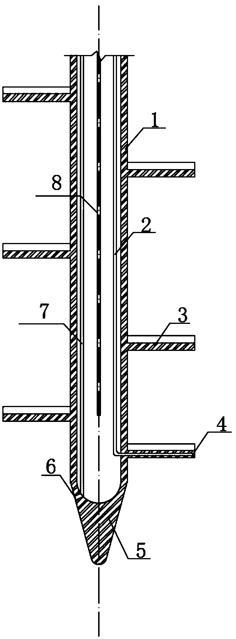
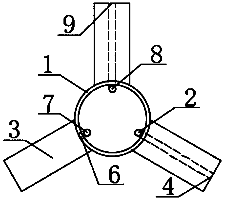
[0013] See attached Figure 1 ~ Figure 2 , the present invention consists of a drill bit 5 and a drill pipe 1 provided with a high-pressure grouting pipe 2, a high-pressure water injection pipe 8, a stirring blade 3 and a normal-pressure grouting pipe 7. 7 The high-pressure grouting pipe 2 and the high-pressure water injection pipe 8 arranged in the shape of a character, the high-pressure grouting port 4 of the high-pressure grouting pipe 2 and the high-pressure water injection port 9 of the high-pressure water injection pipe 8 are arranged on the mixing blade 3 near the drill bit 5 down, and the high-pressure water jet 9 is above the high-pressure grouting port 4; the normal-pressure spout 6 of the normal-pressure grouting pipe 7 is arranged at the joint of the drill bit 5 and the drill pipe 1, and is connected with the high-pressure grouting port 3 and The high-pressure water jets 9 carry out rotary spraying and stirring to the soil together.

[0014] The present invention ...


PUM


Abstract

The invention discloses a double-high-pressure jet grouting stirring drill bit and a construction method thereof. The stirring drill bit comprises a drill bit body and a drill rod provided with stirring blades, wherein a normal-pressure grouting pipe is arranged in the drill rod, a high-pressure grouting pipe and a high-pressure water injection pipe which are arranged in a delta shape with the normal-pressure grouting pipe are arranged in the drill rod, a high-pressure slurry spraying opening of the high-pressure grouting pipe and a high-pressure water spraying opening of the high-pressure water injection pipe are formed below the stirring blades close to the drill bit body, the high-pressure water spraying opening is formed above the high-pressure slurry spraying opening, a normal-pressure nozzle of the normal-pressure grouting pipe is arranged at the joint of the drill bit body and the drill rod, and the normal-pressure nozzle, the high-pressure slurry spraying opening and the high-pressure water spraying opening jointly conduct rotary spraying, stirring and cutting on a soil body. Compared with the prior art, the double-high-pressure jet grouting stirring drill bit has the advantages of simple structure, large pile forming diameter, good pile forming quality, high construction speed and the like.

Description

technical field [0001] The invention relates to the technical field of pile foundation drilling rigs, in particular to a rotary jet stirring drill bit used for large-diameter rotary pile support structures. Background technique [0002] At present, domestic support for deep foundation pits generally adopts the support structure of stirring piles. For example, the retaining wall of gravity retaining support adopts biaxial and triaxial technology. Due to the limited diameter of the hole formed by the stirring drill bit, the diameter of the pile hole is small. , there are many overlaps between piles, the construction speed is slow, and the quality of the supporting structure is easily affected; the reinforcement of deep foundation pits generally adopts biaxial, triaxial and rotary grouting, etc., and the engineering volume is large. , the pile-forming speed is slow, resulting in longer construction period and higher project cost. [0003] The agitating drill bits or rotary jet...

Claims


Application Information

Patent Timeline
IPC IPC(8): E02D5/46
CPCE02D5/46
Inventor 周玉石谢晓东刘国锋谢曙东鲍国强张群耿良才
Owner SHANGHAI CHENGDI CONSTR
Features
  • R&D
  • Intellectual Property
  • Life Sciences
  • Materials
  • Tech Scout
  • Unparalleled Data Quality
  • Higher Quality Content
  • 60% Fewer Hallucinations
Learn More