A hoisting combined power unit frame

A power unit and combined technology, which is applied in the field of hoisting combined power unit frame, can solve the problems of unfavorable fans, air ducts and optimal layout design of heat dissipation components, reduce the failure rate of auxiliary power units, and occupy convenient positions for maintenance, etc., to achieve Conducive to optimal design, facilitate structural optimization design, and improve maintainability

Active Publication Date: 2021-06-01
XIAN YONGDIAN ELECTRIC
View PDF10 Cites 0 Cited by
  • Summary
  • Abstract
  • Description
  • Claims
  • Application Information

AI Technical Summary

Problems solved by technology

However, this installation method has the following disadvantages: ①The frame is only used for the mechanical support and installation positioning of the power unit itself, and other machined parts such as screws need to be added for mechanical fixing, which is not convenient for installation and maintenance; ②With the development of power unit control and protection technology Mature, the failure rate of the auxiliary power unit has been greatly reduced but still occupies a convenient position for maintenance; ③The installation layout of this power unit is not conducive to the optimal layout of fans, air ducts and heat dissipation components when the converter is air-cooled and heat-dissipated design
However, this one-piece frame has the following disadvantages: 1. It takes up a lot of space and is not convenient for shipping and storage of components; During the butt joint assembly of the inverter, there are combination errors such as machining error, welding error, assembly error, etc., which may easily lead to assembly problems such as hole deviation; 3. The frame is only used as the mechanical support of the power unit itself and the connection and fixation with the converter , does not help to improve the maintainability of the power unit

Method used


Image

  • A hoisting combined power unit frame
  • A hoisting combined power unit frame
  • A hoisting combined power unit frame

Examples


Embodiment

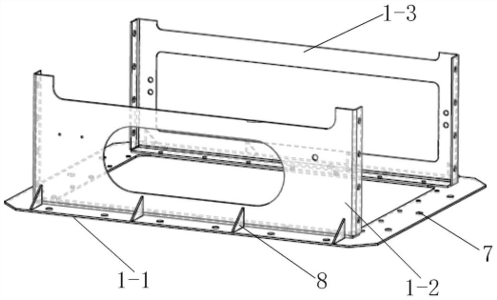
[0029] see Figure 1-3 As shown, the present invention provides a hoisting combined power unit frame, including a frame main body 1 and an assembly frame symmetrically installed on the frame main body 1,

[0030] The frame body 1 includes a frame bottom plate 1-1 at its bottom, the frame bottom plate 1-1 is provided with through holes, and the frame bottom plate 1-1 is fixedly installed on the substrate surface of the radiator 2;

[0031] Front baffle 1-2 and rear baffle 1-3 are installed on the opposite sides of the upper surface of frame bottom plate 1-1, and the left edge, right edge and bottom edge of front baffle 1-2 are all provided with holes facing through holes. Bending, the bending structure of the rear baffle 1-3 and the front baffle 1-2 is the same;

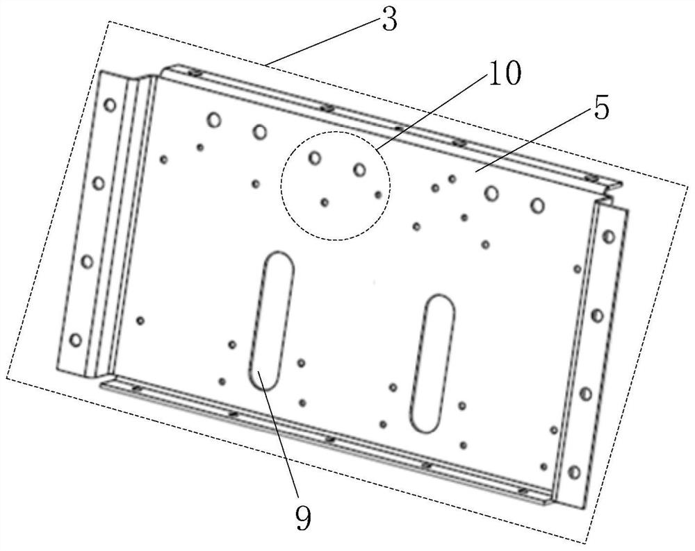
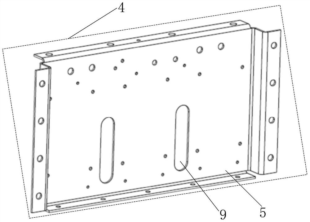
[0032] The assembly frame includes a left assembly frame 3 and a right assembly frame 4. The left assembly frame 3 includes a left assembly frame bottom plate 5 and four side bends distributed on the left assembly fr...


PUM


Abstract

The invention belongs to the technical field of rail transit converter devices, and relates to a hoisting combined power unit frame, comprising a frame body and an assembly frame. The frame body includes a frame bottom plate, the frame bottom plate is provided with a through hole, and the frame bottom plate is fixedly mounted on a base plate of a radiator Surface; the opposite sides of the upper surface of the frame bottom plate are installed with a front baffle and a rear baffle, and the left edge, right edge and bottom edge of the front baffle are all provided with bending toward the through hole; the assembly frame includes a left assembly frame and a rear baffle. The right assembly frame includes a left assembly frame bottom plate and four side bends distributed on the left assembly frame bottom plate, and a drive circuit board is installed on the left assembly frame bottom plate. The hoisting combined power unit frame has a compact structure, reduces the total weight and volume of the power unit, effectively saves the space of the converter, and at the same time facilitates installation and maintenance, and does not require the use of other machined components to realize the installation and connection of the power unit and the converter. , which can be flexibly applied to the hoisting and assembly conditions of the EMU.

Description

technical field [0001] The invention belongs to the technical field of rail traffic converter devices, and relates to a power unit frame, in particular to a hoisting combined power unit frame. Background technique [0002] The rail transit vehicle converter device provides power and power for the vehicle system, and is an important part of the rail transit vehicle. As the core component of the converter device, the power unit performs power conversion on the input voltage of the rail vehicle converter, and has also been widely used and developed rapidly. With the development and application of high-power semiconductor device IGBT, the auxiliary power unit of rail transit vehicles is also developing in the direction of unitization and high reliability. The rail vehicle converter is hoisted at the bottom of the carriage. The frame is the overall structural support of the power unit and an important part connected with the converter. The maintainability and availability of its...

Claims


Application Information

Patent Timeline
Patent Type & Authority Patents(China)
IPC IPC(8): H05K7/18
CPCH05K7/18
Inventor 马瑞丁巧娅高永军刘雄张丹
Owner XIAN YONGDIAN ELECTRIC
Why Eureka
Try Eureka