
U-shaped magnetic levitation rail transit beam

A magnetic levitation track and transportation technology, which is applied in the field of rail transportation, can solve problems such as safety problems of high-altitude operations, inconvenient daily maintenance, etc., and achieve the effect of matching and harmonious appearance with the environment, large working space, and increased lateral rigidity

Pending Publication Date: 2020-05-29
CHINA RAILWAY 23RD BUREAU GRP RAILTRANSIT ENG CO LTD +2
View PDF3 Cites 3 Cited by
  • Summary
  • Abstract
  • Description
  • Claims
  • Application Information

AI Technical Summary

Problems solved by technology

[0007] To sum up, none of the existing maglev track beam structures can perfectly solve the safety problems of high-altitude operations, the inconvenient problems of daily maintenance and the need to build additional emergency evacuation channels at the same time

Method used


Image

  • U-shaped magnetic levitation rail transit beam
  • U-shaped magnetic levitation rail transit beam
  • U-shaped magnetic levitation rail transit beam

Examples


Embodiment 1

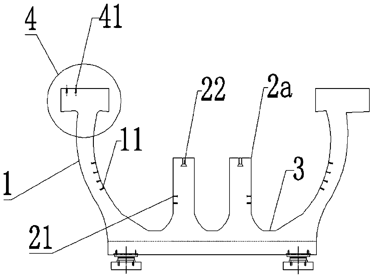
[0038] Such as figure 1 Shown is the sectional structure of a single-line rail transit beam with a built-in U-shaped track support, including an outer U-shaped beam body 1 and a U-shaped track support 2a placed inside the beam body 1 . Wherein, the bottom of the U-shaped track support 2a is integrated with the bottom of the beam body 1, and the whole adopts a prestressed reinforced concrete structure.

[0039] In addition, the two arms of the beam body 1 are two wing plates, and wing edges 4 are arranged on the top of the wing plates, and a number of fourth embedded nuts 41 for installing sound barriers are arranged on the outside of the top surface of the wing edges 4 . Among them, the outer width of the top surface of the wing edge 4 should not be less than 800mm, so as to facilitate the installation of equipment such as signal and sound barriers.

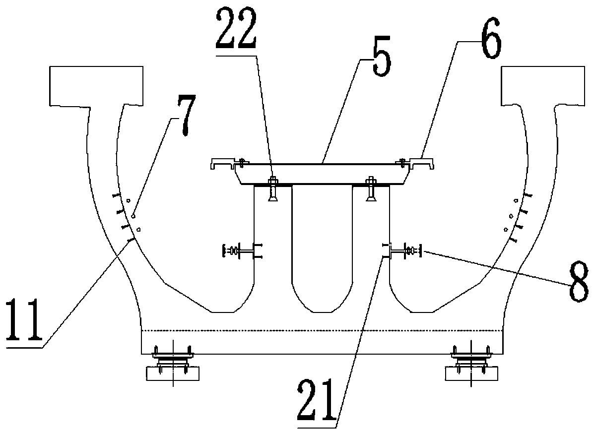
[0040] On the inner wall of the beam body 1, there are several first embedded nuts 11 for installing the cables 7; where the ...

Embodiment 2

[0054] Such as Figure 6 As shown in , another implementation structure of this program is to change the structure of the U-shaped track support 2a in Example 1 into a Π-shaped track support 2b, and keep other parts unchanged. After this change, its advantage is: the magnetic levitation plate 6 can be directly installed on the two ends of the Π-shaped track support 2b, so that the steel sleeper can be saved, thereby further reducing the total investment cost of the magnetic levitation rail transit.

[0055] Among them, the section structure of the double-line rail transit beam with built-in Π-shaped track support, such as Figure 7 As shown, on the pier 10, two double-line rail transit beams with built-in Π-shaped track supports are arranged side by side in parallel, and in the middle, two wing edges 4 are spliced ​​together to directly form an emergency evacuation passage 9.


PUM

PropertyMeasurementUnit
Outside widthaaaaaaaaaa

Abstract

The invention discloses a U-shaped maglev rail transit beam, which is characterized by comprising an outer U-shaped beam body and a U-shaped or n-shaped rail support arranged in the beam body, the bottom of the rail support is connected with the bottom of the beam body into a whole; the height of the rail support is lower than that of the beam body, and the height of the beam body is flush with atrain floor; a mounting channel is arranged between the beam body and the rail support; two arms of the outer U-shaped beam body are two wing plates, and wing edges are arranged at the top ends of thewing plates. By the adoption of the scheme, aloft work is not needed when the magnetic levitation track beam is constructed, daily maintenance and overhaul are convenient, the emergency evacuation passage is arranged during double-line assembly, and compared with a traditional structure, the defects in the prior art are overcome, and the construction cost is reduced.

Description

technical field [0001] The invention relates to the technical field of rail transit, in particular to a U-shaped maglev rail transit beam. Background technique [0002] At present, the known magnetic levitation technology was first proposed by German engineer Herman Kemper, and in 1934 he applied for a patent for the magnetic levitation train. However, my country began to study maglev trains in the 1980s. [0003] The maglev track beam is the carrier of the maglev train and has a strong binding force on the train. The current common maglev track beams have the following three representative structures: [0004] First, the monolithic composite rectangular beam represented by the patent "Prefabricated Reinforced Concrete Medium and Low Speed ​​Magnetic Levitation Beam and Its Production Method" (CN105297561B) needs to add an emergency evacuation platform and steel structure separately in its structure, and the maintenance cost is relatively high . The laying of tracks, pow...

Claims


Application Information

Patent Timeline
IPC IPC(8): E01B25/30E01D2/00
CPCE01B25/305E01D2/00
Inventor 林晓波谭斌徐闯李良才刘延龙郭俊峰翟勇张彪陆清元奚成李大源张蕾龚俊虎崔阳华谢海林鄢巨平李伟强
Owner CHINA RAILWAY 23RD BUREAU GRP RAILTRANSIT ENG CO LTD
Features
  • Generate Ideas
  • Intellectual Property
  • Life Sciences
  • Materials
  • Tech Scout
  • Unparalleled Data Quality
  • Higher Quality Content
  • 60% Fewer Hallucinations
Learn More