Maglev train-ground communication infrastructure deployment method

A technology for maglev trains and infrastructure, applied in communication between vehicles and infrastructure, vehicle wireless communication services, wireless communication, etc., can solve problems such as poor communication service quality, high failure rate, and reduced system robustness. Achieve centralized management, avoid frequent switching, and increase coverage

Active Publication Date: 2020-06-02
BEIHANG UNIV
View PDF9 Cites 3 Cited by
  • Summary
  • Abstract
  • Description
  • Claims
  • Application Information

AI Technical Summary

Problems solved by technology

For communication scenarios in higher frequency bands, if an antenna is set up at the base station for transmission and reception, and the transmission power and transmission gain of the antenna are not specially designed, then the coverage radius of a base station will be very small. When the train is running at high speed, it will Causes extremely frequent handoffs, which will lead to extremely unstable communication links and a sharp decrease in system robustness
[0006] Now the high-speed rail directly communicates with the base station on the ground, and the moving speed is fast, handover is frequent, and the failure rate is high. Therefore, the quality of communication service on the high-speed rail is very poor, and it is often impossible to connect to the Internet or make calls.
If the maglev train uses the same communication system as the high-speed rail, the communication link will be more unstable

Method used


Image

  • Maglev train-ground communication infrastructure deployment method
  • Maglev train-ground communication infrastructure deployment method
  • Maglev train-ground communication infrastructure deployment method

Examples


Embodiment Construction

[0058] The present invention will be described in detail below in conjunction with the accompanying drawings.

[0059] A method for deploying the vehicle-ground communication infrastructure of a maglev train according to the present invention can be applied not only to transmission scenarios of safety data such as train control, but also to transmission scenarios of high-throughput non-safety data facing passengers; this embodiment mainly Expand and describe the transmission scenarios of train control safety data.

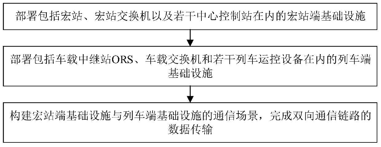
[0060] The communication infrastructure deployment method described, such as figure 1 As shown, the specific steps are as follows:

[0061] Step 1. Deploy macro station infrastructure including macro stations, macro station switches, and several CCS (central control stations);

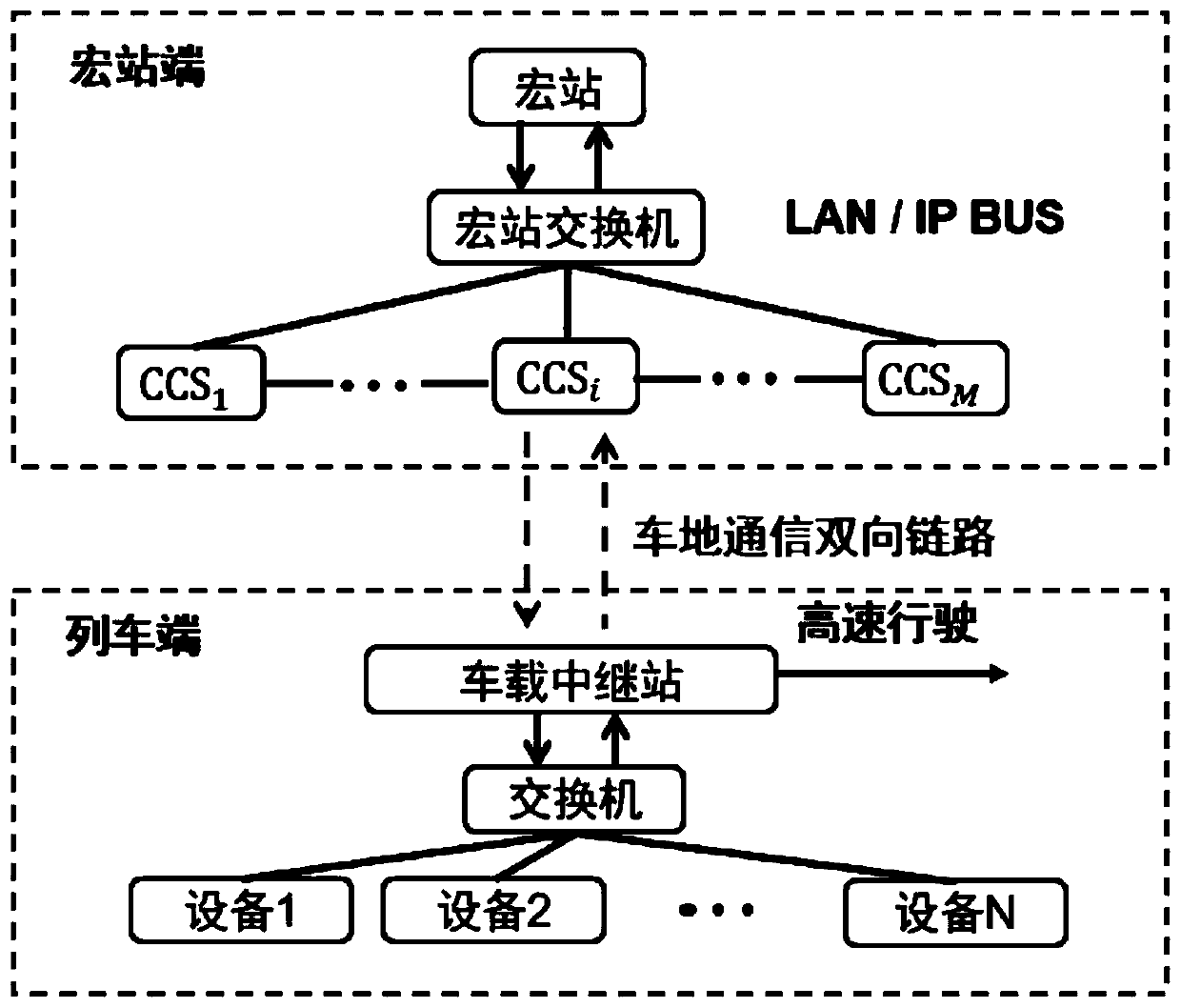
[0062] Such as figure 2 As shown in , the macro station is connected to several CCSs through optical cables through the macro station switch;

[0063] Each CCS is deployed at equal int...


PUM


Abstract

The invention discloses a maglev train-ground communication infrastructure deployment method, and belongs to the technical field of ground traffic train-ground communication. The method comprises thefollowing steps: firstly, deploying macro station end infrastructures including a macro station, a macro station switch and a plurality of CCSs, deploying a plurality of RAUs at equal intervals in ascattered manner in each CCS coverage range, adopting a distributed structure for an antenna configured for each CCS, and zooming out through a DRoF; and then deploying train end infrastructures including an on-board relay station (ORS), an on-board switch and a plurality of train operation control devices; collecting the data of each train operation control device to the ORS for unified processing; connecting the ORS with the vehicle-mounted antenna unit through the DRoF, and arranging the vehicle-mounted antenna unit at the head and the tail of the train to realize diversity reception; and finally, constructing a communication scene of the macro station end infrastructure and the train end infrastructure, and completing data transmission of the bidirectional communication link. Accordingto the invention, the coverage area of the cell is increased, and frequent switching of the maglev train in the high-speed advancing process is avoided; power loss is very low.

Description

technical field [0001] The invention belongs to the technical field of vehicle-ground communication for ground transportation, and specifically relates to a method for deploying vehicle-ground communication infrastructure of a maglev train, which is used to increase the coverage of vehicle-ground communication, avoid frequent switching, and improve the robustness of vehicle-ground communication in high-speed mobile scenarios sex. Background technique [0002] The maglev train is a modern high-tech rail vehicle. Japan set a new superconducting maglev speed record of 603km / h on the Yamanashi test line in 2015. Whether it is a traditional wheel-rail train or a faster maglev train, the communication between the train and the ground control center is very important. It is necessary to ensure that the train control data can be transmitted in real time and reliably. The high moving speed of the maglev train undoubtedly brings difficulties to the design of the vehicle-ground commun...

Claims


Application Information

Patent Timeline
IPC IPC(8): H04W4/44H04W4/42H04W36/18H04B7/26H04B10/2575H04W36/04H04W88/08
CPCH04B7/2609H04B10/25754H04W4/42H04W4/44H04W36/04H04W36/18H04W88/085Y02D30/70
Inventor 肖振宇李大鹏董航
Owner BEIHANG UNIV
Why Eureka
Try Eureka