Special-shaped thin-walled part fastening mechanism

A technology for thin-walled parts and fastening mechanisms, which is applied in the field of fastening mechanisms for special-shaped thin-walled parts. It can solve problems such as difficult parts processing and mass production, high surface finish requirements, clamping tool clamping, etc., and achieve positioning accuracy. High, low labor intensity, stable push and pull effect

Pending Publication Date: 2020-06-05
SUZHOU VOCATIONAL UNIV
View PDF0 Cites 1 Cited by
  • Summary
  • Abstract
  • Description
  • Claims
  • Application Information

AI Technical Summary

Problems solved by technology

Therefore, it is difficult for the general clamping method to meet the processing requirements and characteristics of such parts. In order to improve production efficiency, reduce production costs, and achieve processing accuracy and consistency, it is necessary to design special positioning and fastening for the processing and manufacturing of such parts. mechanism to meet the processing requirements and characteristics of such parts, while ensuring production while also considering improving production efficiency
[0003] At present, special-shaped thin-walled parts are characterized by thin walls, high dimensional accuracy, high shape requirements, high surface finish requirements, difficult clamping, and easy deformation. Therefore, when considering the manufacturing process of such parts, conventional processes and assembly clamping method, it is often difficult to meet the needs of parts processing and mass production, such as Figure 7 and 8 A special-shaped thin-walled part is shown, which is characterized by thin-walled, special-shaped, curved and inclined surfaces on the inside and outside, and it is impossible to use a general-purpose clamping tool to clamp the part, which brings great difficulties to the production and manufacturing. confusion

Method used


Image

  • Special-shaped thin-walled part fastening mechanism
  • Special-shaped thin-walled part fastening mechanism
  • Special-shaped thin-walled part fastening mechanism

Examples


Embodiment Construction

[0038] The present invention will be further explained below in conjunction with the accompanying drawings and specific embodiments. It should be understood that the following specific embodiments are only used to illustrate the present invention and are not intended to limit the scope of the present invention. It should be noted that the words "front", "rear", "left", "right", "upper" and "lower" used in the following description refer to the directions in the drawings, and the words "inner" and "outer ” refer to directions towards or away from the geometric center of a particular part, respectively.

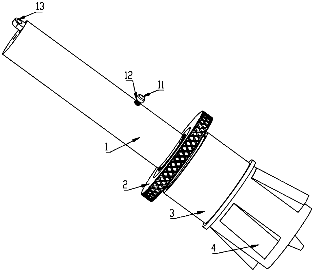
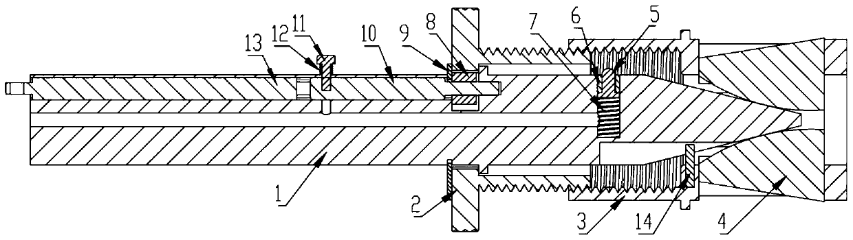
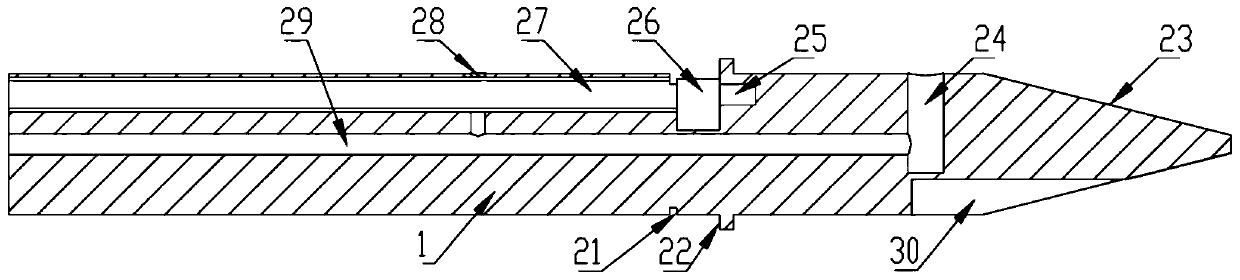
[0039] As shown in the figure, a fastening mechanism for special-shaped thin-walled parts includes a mandrel 1, a locking sleeve 2, a cage 3 and a tension block 4. The mandrel 1 is composed of cylindrical parts and conical parts arranged on the left and right. And the central axes of the cylindrical part and the conical part are collinear, a motor 10 and a battery 13 connected ...


PUM


Abstract

The invention provides a special-shaped thin-walled part fastening mechanism. The special-shaped thin-walled part fastening mechanism comprises a core shaft, a locking sleeve, a cage and tension blocks. The core shaft is composed of a cylinder piece and a cone piece. The cylinder piece of the core shaft is internally provided with a motor and a battery connected with the motor in a matched mode. Amotor shaft of the motor is arranged to the right, and the motor shaft is parallel to the central axis of the cylinder piece. A gear is installed at the right end of the motor shaft of the motor, thelocking sleeve sleeves the core shaft, an inner gear meshed with the gear is arranged in the left end of the locking sleeve, the right end of the locking sleeve is in threaded connection with the left end of the cage, the left end of the cage sleeve outside the right end of the locking sleeve, tension block positioning grooves adapted to the tension blocks are uniformly formed in the right end ofthe cage in the circumference direction. The special-shaped thin-walled part fastening mechanism has the beneficial effects that the structure is simple and clear, the use is convenient and fast, thin-walled parts can be conveniently and accurately placed on the fastening mechanism, and can be locked and loosened by the motor, so that the electromechanical integration is realized.

Description

technical field [0001] The invention relates to the technical field of special-shaped thin-walled parts, in particular to a fastening mechanism for special-shaped thin-walled parts. Background technique [0002] With the development of science and technology, products that meet the needs of the new era emerge in endlessly. The shapes and appearances of various product shell parts and mechanical parts are becoming more and more complicated, and the forms are also diversified. In order to meet the requirements of beautiful and practical products, a large number of The curved surface design is used in various products, which puts forward more and higher requirements for the manufacture and process of product parts. It is necessary to use innovative thinking to find more suitable methods to deal with irregular appearance parts and complex parts. Manufacture of shape parts. Especially in the 3C industry with a wide range of products, short product cycles, and endless new product...

Claims


Application Information

Patent Timeline
Patent Type & Authority Applications(China)
IPC IPC(8): B23B31/40
CPCB23B31/4066
Inventor 顾星宦奕盖立武朱玮吴峻峰黄立平
Owner SUZHOU VOCATIONAL UNIV
Why Eureka
Try Eureka