Machine for automatically assembling connecting rod, piston pin and retainer ring

A technology of piston pins and assembly machines, which is applied in assembly machines, metal processing, metal processing equipment, etc., can solve problems such as difficulty in realizing assembly system integration and miniaturization, difficulty in ensuring product quality consistency, and low assembly efficiency. The effects of reducing occupied space, ensuring reliability, and improving assembly efficiency

Active Publication Date: 2020-06-05
重庆炜海自动化科技有限公司
View PDF11 Cites 7 Cited by
  • Summary
  • Abstract
  • Description
  • Claims
  • Application Information

AI Technical Summary

Problems solved by technology

[0002] The crankshaft-connecting rod mechanism is the main mechanism for the engine to generate and output power. It mainly includes the piston extending into the engine, the crankshaft that outputs power, and the connecting rod connecting the piston and the crankshaft. The assembly process of the three involves multiple steps, and the procedure is cumbersome. , if manual assembly is used, the assembly efficiency is low, and it is difficult to ensure the consistency of product quality. Some existing mechanical-assisted automatic assembly equipment on the market has a relatively complicated structure, often takes up a large space, and it is difficult to realize the integration and integration of assembly systems. Miniaturization and low assembly efficiency

Method used


Image

  • Machine for automatically assembling connecting rod, piston pin and retainer ring
  • Machine for automatically assembling connecting rod, piston pin and retainer ring
  • Machine for automatically assembling connecting rod, piston pin and retainer ring

Examples


Embodiment Construction

[0048] The present invention will be further described below in conjunction with embodiment and accompanying drawing.

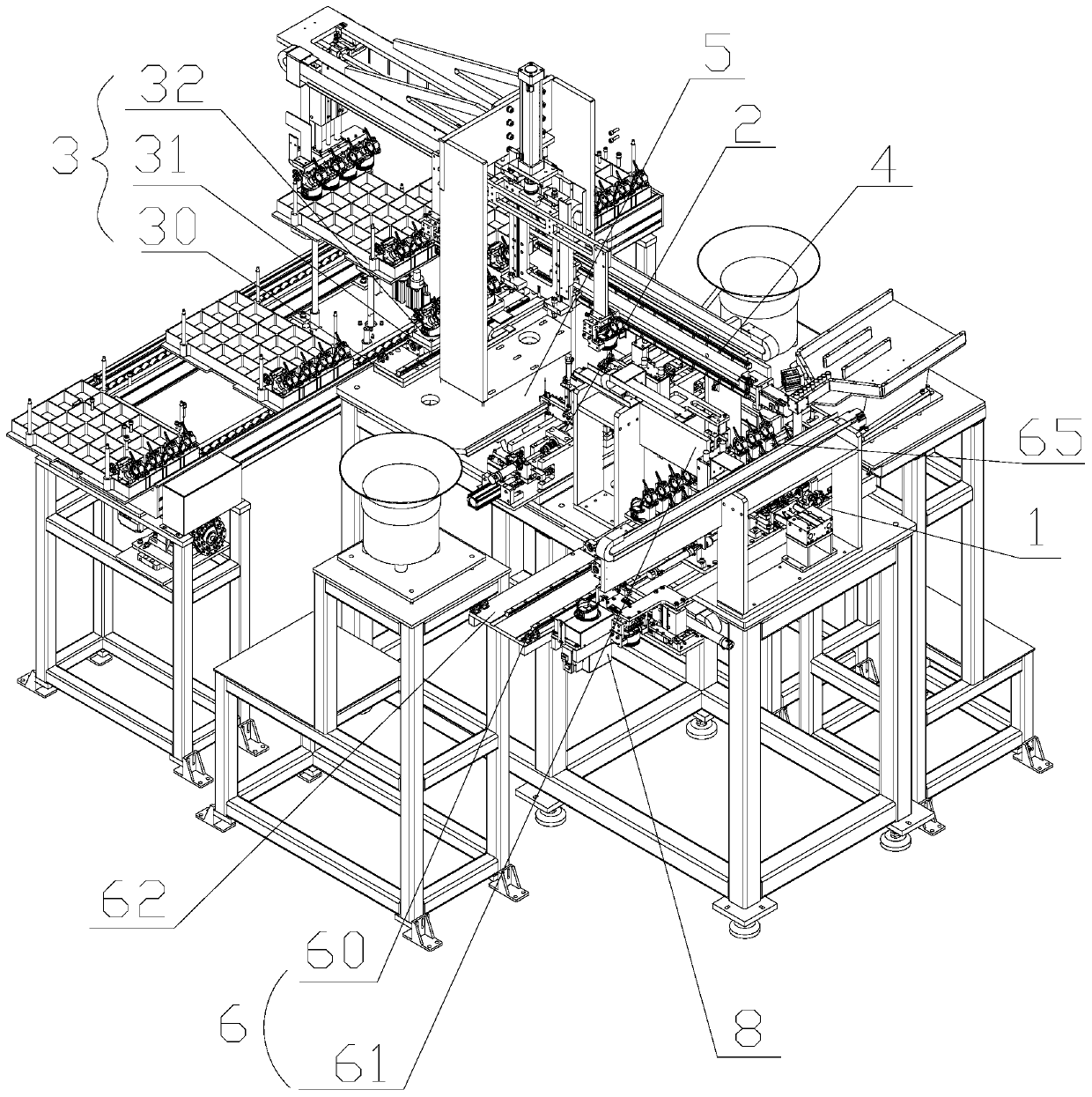
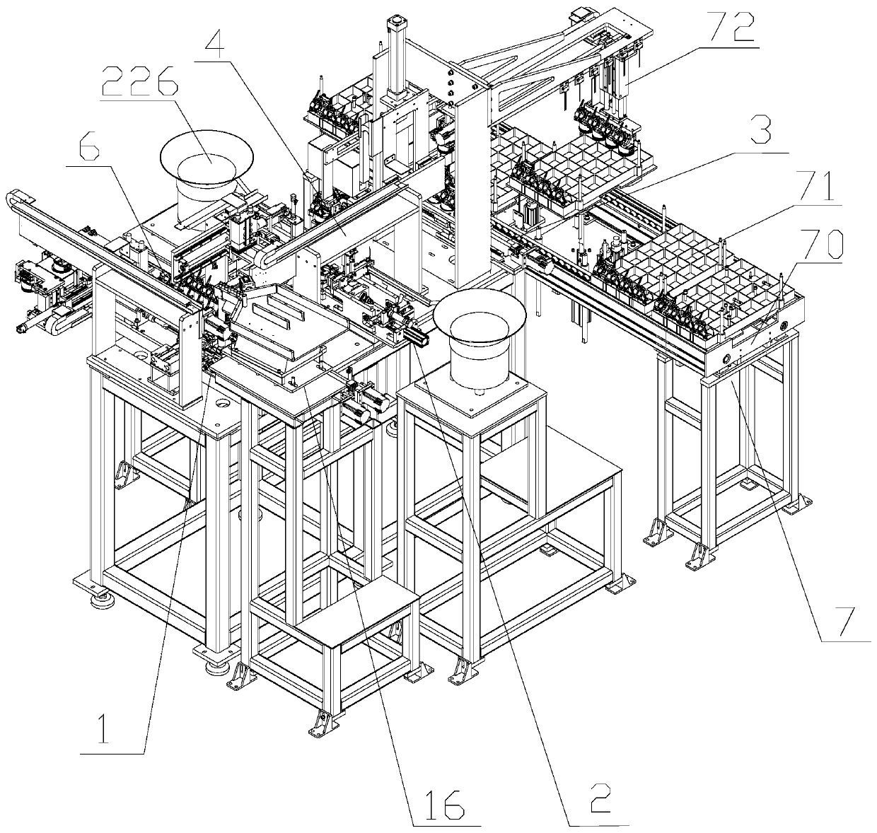
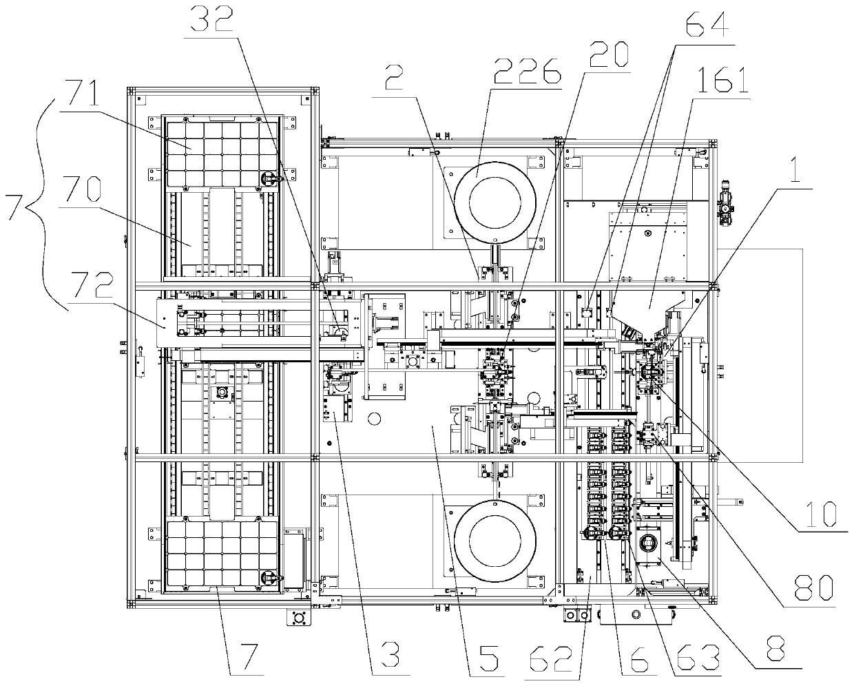
[0049] refer to Figure 1 to Figure 17 , the connecting rod piston pin retaining ring automatic assembly machine of the present invention mainly includes a piston pin pressing line 1, a retaining ring pressing line 2, a finished product temporary storage line 3 and a finished product conveying line 7, as shown in the figure, the piston pin pressing line 1. The retaining ring press-fitting line 2 and the finished product temporary storage line 3 are all installed on the same workbench 5, and the three are arranged in parallel in turn, basically at the same level, and the finished product conveying line 7 is located on the finished product temporary storage line 3 away from the retaining ring On one side of the press-fitting line 2, the piston pin press-fitting line 1 is mainly used to complete the installation of the piston pin and realize the fixed connection...


PUM


Abstract

The invention discloses a machine for automatically assembling a connecting rod, a piston pin and a retainer ring. The machine comprises a workbench, wherein a piston pin press-assembly line, a retainer ring press-assembly line and a finished product temporary storage line are sequentially arranged on the workbench in parallel; a material taking and unloading grab assembly is arranged among the piston pin press-assembly line, the retainer ring press-assembly line and the finished product temporary storage line, and provided with a material taking grab and a material unloading grab; the material taking grab and the material unloading grab are connected with the same movable auxiliary plate; the piston pin press-assembly line is provided with a piston positioning seat A; the retainer ring press-assembly line is provided with a piston positioning seat B; the finished product temporary storage line comprises a base plate C and a storage table movably arranged on the base plate C; and the storage table is provided with at least one piston positioning groove and slides along the length direction of the base plate C so that the piston positioning groove can be collinear with the piston positioning seat A and the piston positioning seat B. According to the scheme, the overall layout structure is compact, the occupied space is greatly reduced, parts are simplified, the mechanism is optimized, the assembly efficiency is improved, meanwhile, the cost is reduced, and the system operation reliability is guaranteed.

Description

technical field [0001] The invention belongs to the field of automatic assembly equipment, and in particular relates to an automatic assembly machine for a connecting rod piston pin retaining ring. Background technique [0002] The crankshaft-connecting rod mechanism is the main mechanism for the engine to generate and output power. It mainly includes the piston extending into the engine, the crankshaft that outputs power, and the connecting rod connecting the piston and the crankshaft. The assembly process of the three involves multiple steps, and the procedure is cumbersome. , if manual assembly is used, the assembly efficiency is low, and it is difficult to ensure the consistency of product quality. Some existing mechanical-assisted automatic assembly equipment on the market has a relatively complicated structure, often takes up a large space, and it is difficult to realize the integration and integration of assembly systems. Miniaturization and low assembly efficiency. ...

Claims


Application Information

Patent Timeline
Patent Type & Authority Applications(China)
IPC IPC(8): B23P21/00B23P19/02B23P19/00
CPCB23P19/001B23P19/02B23P21/004
Inventor 戴建良张雷元孙登明
Owner 重庆炜海自动化科技有限公司
Why Eureka
Try Eureka