
Rotatable hydraulic cantilever lifting device

A hydraulic and cantilever technology, applied in the direction of transportation and packaging, cranes, etc., can solve the problems of easy shaking, difficult to guarantee precision, difficult to control precision, etc., and achieve the effect of stable lifting process, fast lifting and large lifting capacity

Pending Publication Date: 2020-06-05
SHANGHAI HELI HYDRAULIC MECHANICAL & ELECTRICAL CO LTD
View PDF0 Cites 1 Cited by
  • Summary
  • Abstract
  • Description
  • Claims
  • Application Information

AI Technical Summary

Problems solved by technology

[0005] In practical application, the cantilever crane relies on the motor to drive the reel to control the lifting and lowering of heavy objects. It is difficult to guarantee its accuracy on the running line, and the straightness and height positioning are not accurate.
At the same time, the steel wire rope is used as the main force-bearing member. The steel wire rope itself is not rigid enough, and the heavy object is unstable during the process of lifting and rotating, and it is easy to cause the possibility of shaking or even tipping over.
As a common lifting machine in the market, the electric hoist itself is not stable enough, and it is prone to failures such as wire rope grooving and breakage, and even production safety accidents in severe cases.
[0006] Therefore, how to solve the defects of the existing cantilever hoists such as unstable operation, difficult to control precision, and frequent daily maintenance has become a technical problem urgently needed by those skilled in the art.

Method used


Image

  • Rotatable hydraulic cantilever lifting device
  • Rotatable hydraulic cantilever lifting device
  • Rotatable hydraulic cantilever lifting device

Examples


Embodiment

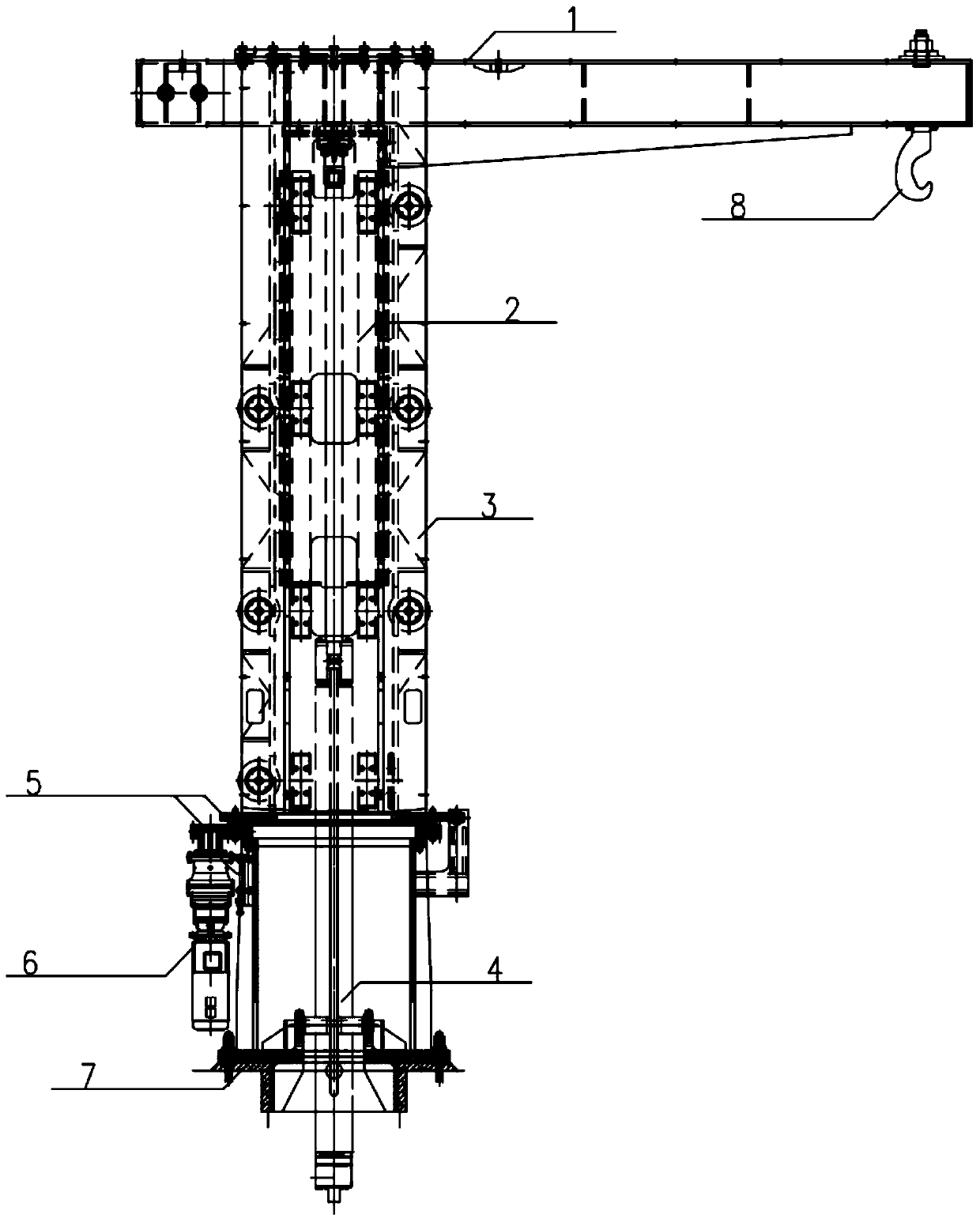
[0049] Such as figure 1 As shown, the rotatable hydraulic cantilever lifting device includes a lifting arm 1 , a base 7 and a hook 8 .

[0050] Wherein, the base 7 is fixed on the civil foundation; one side of the base 7 is provided with a rotating motor 6;

[0051] The upper end of the base 7 is sequentially provided with a slewing bearing 5 and an outer cylinder 3 of the lifting device; the outer cylinder 3 of the lifting device is connected by a slewing pair formed by the slewing bearing 5 and the base 7 with a vertically arranged rotary shaft;

[0052] The outer cylinder 3 of the lifting device is driven to rotate by a rotating motor 6;

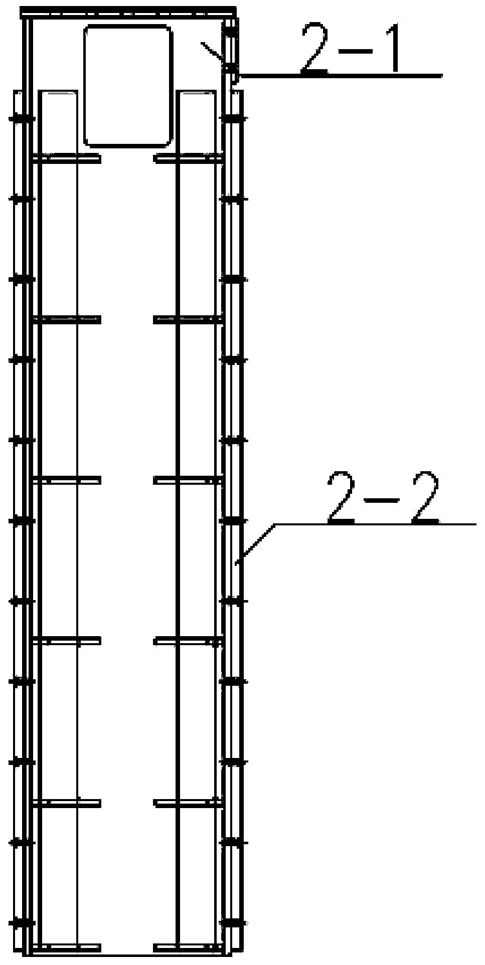
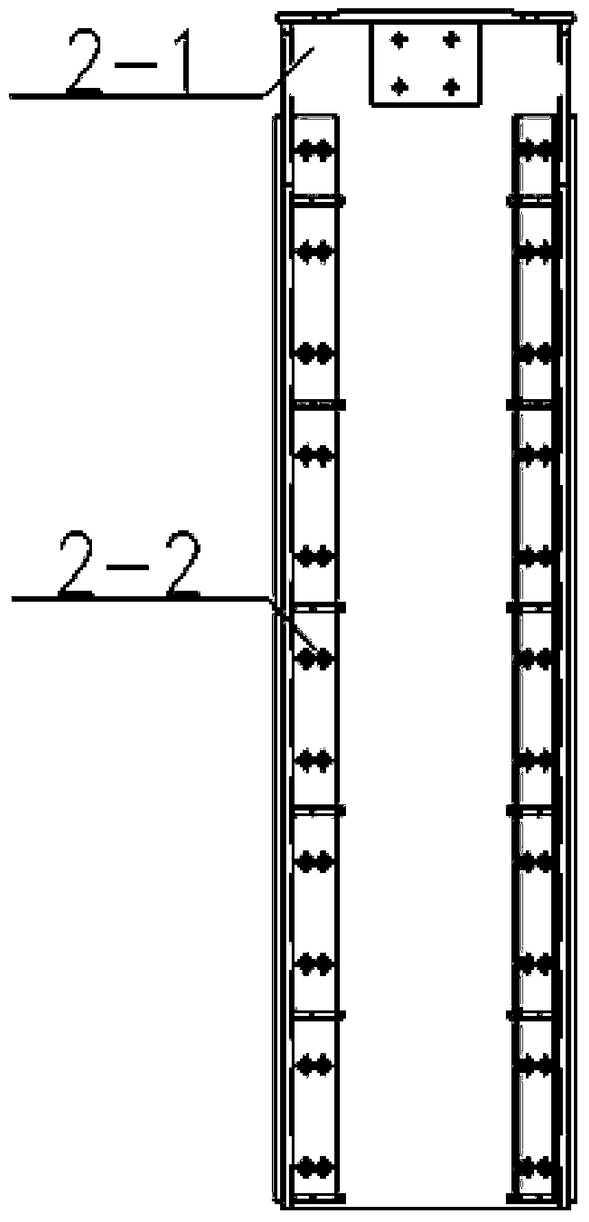
[0053] The inner cylinder 2 of the lifting device is arranged in the outer cylinder 3 of the lifting device. There is a moving pair between the outer cylinder 3 of the lifting device and the inner cylinder 2 of the lifting device. The inner cylinder 2 of the lifting device can move back and forth along the vertical direction; the inner c...


PUM


Abstract

The invention discloses a rotatable hydraulic cantilever lifting device. The rotatable hydraulic cantilever lifting device comprises a lifting arm, a base and a lifting hook, the base is fixed on a civil foundation; a slewing bearing and a lifting device outer cylinder are sequentially arranged at the upper end of the base; the lifting device outer cylinder is connected through a rotary pair whichis formed by the slewing bearing and the base and has a vertically arranged rotary shaft, and is driven by a rotary motor; a lifting device inner cylinder forming a moving pair with the lifting device outer cylinder is arranged in the lifting device outer cylinder; a lifting arm is arranged at the upper end of the lifting device inner cylinder; the base, the slewing bearing, the lifting device inner cylinder and the lifting device outer cylinder are each of a hollow tubular structure, and a hydraulic lifting device is arranged in the tubular structure; the hydraulic lifting device comprises ahydraulic cylinder; a piston rod of the hydraulic cylinder is vertically arranged, and the upper end is in rotary pair connection with the lifting device inner cylinder and the lifting arm. The lifting position, the lifting speed and the rotating angle can be accurately controlled, lifting and rotating can be achieved with high precision, the site can be more fully utilized, and the device can play a role in a narrow space.

Description

technical field [0001] The invention relates to the technical field of manufacturing heavy-duty lifting equipment, in particular to a rotatable hydraulic boom lifting device. Background technique [0002] Cantilever hoists are currently widely used. In the existing cantilever hoist, it is generally composed of a guide rail, an electric hoist, a motor, a column, an electrical control system, a lifting hook or a pallet. [0003] In the prior art, generally the electric hoist (composed of a motor and a reel) works to drive the wire rope to realize lifting and landing of heavy objects. The base at the lower end of the column is fixed on the concrete foundation through anchor bolts, and the motor drives the reducer drive device to rotate the cantilever, and the electric hoist operates back and forth on the cantilever I-beam. [0004] The jib crane has the characteristics of simple structure, convenient operation, small footprint, and large operating range. Therefore, cantileve...

Claims


Application Information

Patent Timeline
IPC IPC(8): B66C23/16B66C23/62B66C23/80B66C23/86
CPCB66C23/163B66C23/62B66C23/80B66C23/86B66C2700/03
Inventor 汪昌润郭家奇赵春禾宋涛
Owner SHANGHAI HELI HYDRAULIC MECHANICAL & ELECTRICAL CO LTD
Learn More