
Road asphalt paving and compacting device

A compacting device and road asphalt technology, which is applied in the direction of roads, roads, road repairs, etc., can solve the problems of low work efficiency and single function, and achieve the effect of adjusting the leveling thickness

Pending Publication Date: 2020-06-05
陈嘉宇
View PDF12 Cites 21 Cited by
  • Summary
  • Abstract
  • Description
  • Claims
  • Application Information

AI Technical Summary

Problems solved by technology

[0003] Asphalt concrete is basically laid on roads now, and the existing asphalt laying device has a single structure and function and low work efficiency

Method used


Image

  • Road asphalt paving and compacting device
  • Road asphalt paving and compacting device
  • Road asphalt paving and compacting device

Examples


Embodiment 1

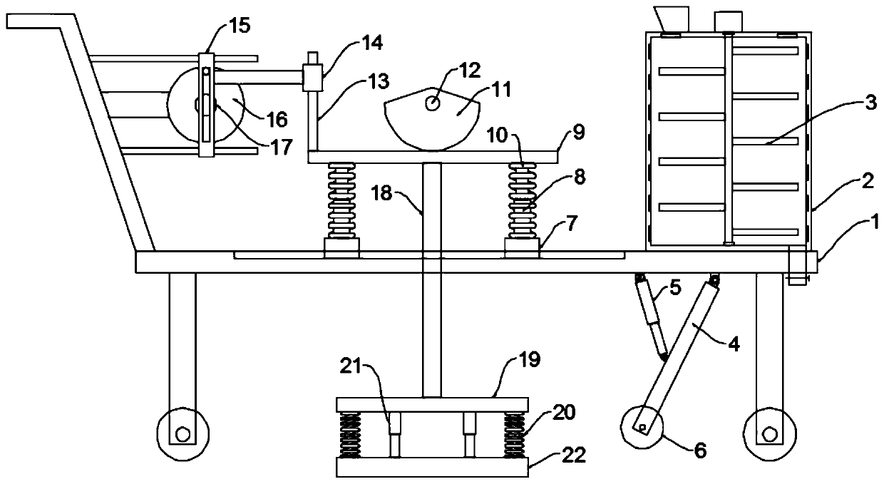
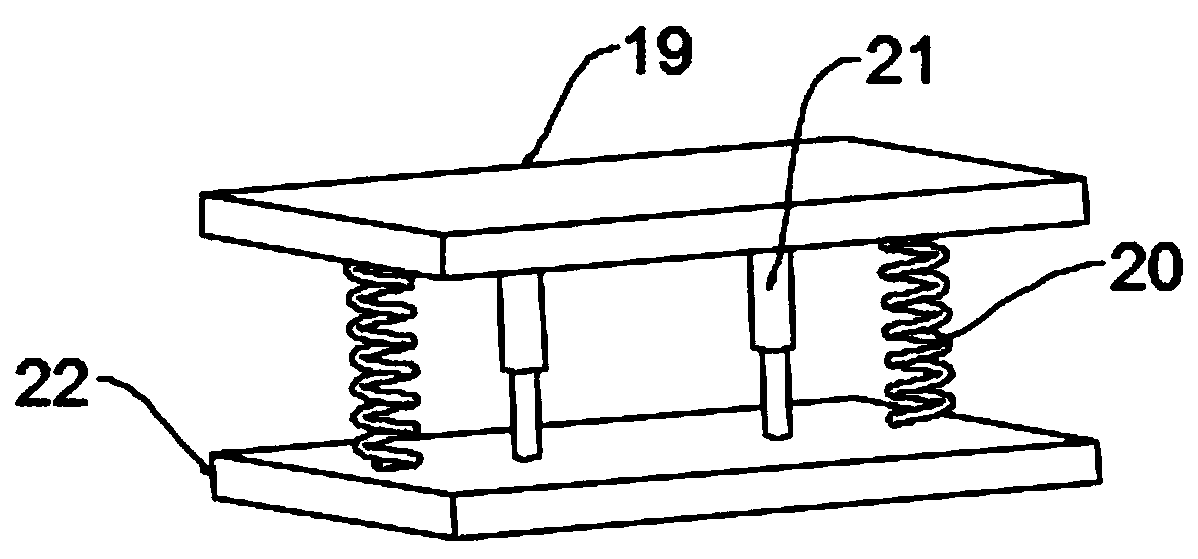
[0024] see Figure 1~2 , in an embodiment of the present invention, a road asphalt paving and compacting device includes a cart 1 and a paving unit, the cart 1 includes a frame, a hand frame fixed at one end of the frame, and fixed at the bottom of the frame evenly and symmetrically The supporting legs and the rollers installed at the bottom of the supporting legs are self-locking rollers to facilitate the movement of the device. The laying unit is installed on the trolley 1, and the laying unit includes a heating box 2 for heating asphalt and a heating box for heating asphalt. The leveling roller 6 for paving asphalt, the top of the heating box 2 is provided with a feed port, the bottom of the heating box 2 is provided with a discharge port, a valve is installed on the discharge port, and an electric heating element for heating and A stirring unit 3 for stirring. In this embodiment, the stirring unit 3 includes a stirring shaft, a stirring rod fixed on the stirring shaft and ...

Embodiment 2

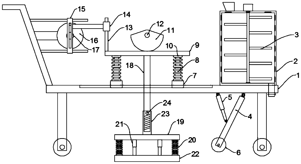
[0027] see image 3The difference between this embodiment of the present invention and Embodiment 1 is that, further, the connecting plate 19 is threadedly connected to the connecting rod 18, the top of the connecting plate 19 is fixed with an internal thread sleeve 23, and the bottom of the connecting rod 18 is provided with There is an external thread that cooperates with the internal thread sleeve 23, and a fastening bolt 24 is also connected between the internal thread sleeve 23 and the connecting rod 18. By adjusting the position of the connecting rod 18 and the connecting plate 19, the pressure of the pressing plate 22 when pressing down can be adjusted. Pressure, better adapt to construction needs.

[0028] The working principle of the present invention is: when working, the first motor 12 drives the sector cam 11 to rotate, and when the arc edge of the convex head of the sector cam 11 contacts the drive plate 9, it drives the drive plate 9 to move downward, and the dri...


PUM


Abstract

The invention discloses a road asphalt paving and compacting device. The device comprises a cart and a laying unit, the laying unit is installed on the cart. The laying unit comprises a heating box used for heating asphalt and a leveling roller used for leveling the asphalt. The road asphalt paving and compacting device further comprises a compacting unit, the compaction unit comprises a pressingplate and a driving assembly used for driving the pressing plate to move. The driving assembly comprises a fan-shaped cam, a driving plate, a driving mechanism used for driving the driving plate to reciprocate left and right, a first telescopic rod, a first spring, a mounting base, a connecting rod and a connecting plate. According to the device, the laying unit is arranged, and the electric pushrod extends or contracts, so that the leveling roller can be driven to rotate through the mounting rod, the distance between the leveling roller and the ground is adjusted, and the effect of adjustingthe leveling thickness is achieved; and the compaction unit is arranged, the pressing plate reciprocates left and right while keeping pressure on asphalt, the compaction area is increased, the compaction effect is better, and the working efficiency is improved.

Description

technical field [0001] The invention relates to the technical field of road construction, in particular to a road asphalt paving and compacting device. Background technique [0002] Asphalt is a dark brown complex mixture composed of hydrocarbons of different molecular weights and their non-metallic derivatives. It is a kind of high-viscosity organic liquid. It is liquid with a black surface and is soluble in carbon disulfide. Asphalt is a waterproof, moisture-proof and anti-corrosion organic gelling material. Pitch can be mainly divided into three types: coal tar pitch, petroleum pitch and natural pitch. Among them, coal tar pitch is a by-product of coking. Petroleum asphalt is the residue after distillation of crude oil. Natural bitumen is stored underground, and some form ore layers or accumulate on the surface of the earth's crust. Asphalt is mainly used in coatings, plastics, rubber and other industries as well as paving roads. [0003] Now on the road, asphalt conc...

Claims


Application Information

Patent Timeline
IPC IPC(8): E01C19/10E01C19/08E01C19/34
CPCE01C19/104E01C19/08E01C19/34
Inventor 陈嘉宇
Owner 陈嘉宇
Learn More