Novel rigidity landfill anti-permeation structure and construction method

A construction method and landfill technology, applied in infrastructure engineering, protective devices, buildings, etc., can solve the problem of not being fully applicable to storage of industrial solid waste and hazardous waste, leaks that cannot be detected and processed in time, and rigid landfill protection. Infiltration structural welding and other issues to achieve the effect of reducing leakage risk, avoiding incompatibility, and preventing environmental pollution accidents

Pending Publication Date: 2020-06-05
CHINA POWER CONSRTUCTION GRP GUIYANG SURVEY & DESIGN INST CO LTD
View PDF0 Cites 7 Cited by
  • Summary
  • Abstract
  • Description
  • Claims
  • Application Information

AI Technical Summary

Problems solved by technology

[0007] The present invention aims to provide a new anti-seepage structure and construction method for rigid landfills to solve the anti-seepage problems of rigid landfills when storing industrial solid wastes and hazardous wastes and the welding problems during the construction of anti-seepage structures
[0008] For the existing flexible landfill disposal technology to dispose of industrial solid waste and hazardous waste, relying solely on the anti-seepage system, once the anti-seepage structure is damaged, there is a risk of causing great damage and pollution to the surrounding environment and the existing lining anti-seepage structure. Reinforced concrete water storage tank technology cannot be fully applied to the storage of industrial solid waste and hazardous waste rigid landfill disposal site, and problems such as leakage cannot be detected and treated in time, the present invention proposes a new type that can be used to store industrial solid waste and hazardous waste. The anti-seepage structure and construction method of the rigid landfill of hazardous waste, the method adopts the following technical scheme:

Method used


Image

  • Novel rigidity landfill anti-permeation structure and construction method
  • Novel rigidity landfill anti-permeation structure and construction method
  • Novel rigidity landfill anti-permeation structure and construction method

Examples


Embodiment Construction

[0042] The present invention will be further described below in conjunction with accompanying drawing and specific embodiment, but should not be interpreted as that the scope of the subject matter of the present invention is only limited to following embodiment, under the situation of not departing from above-mentioned technical thought of the present invention, all according to this field Various modifications, substitutions and alterations made by ordinary technical knowledge and common means are included in the scope of the present invention.

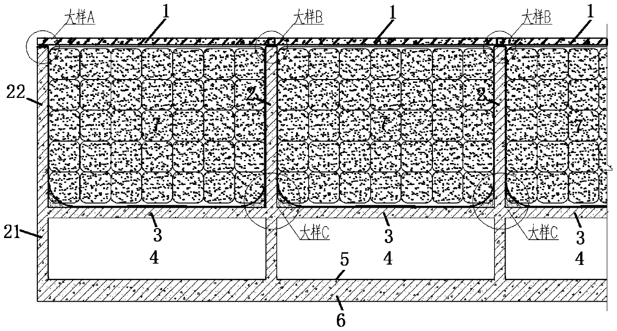
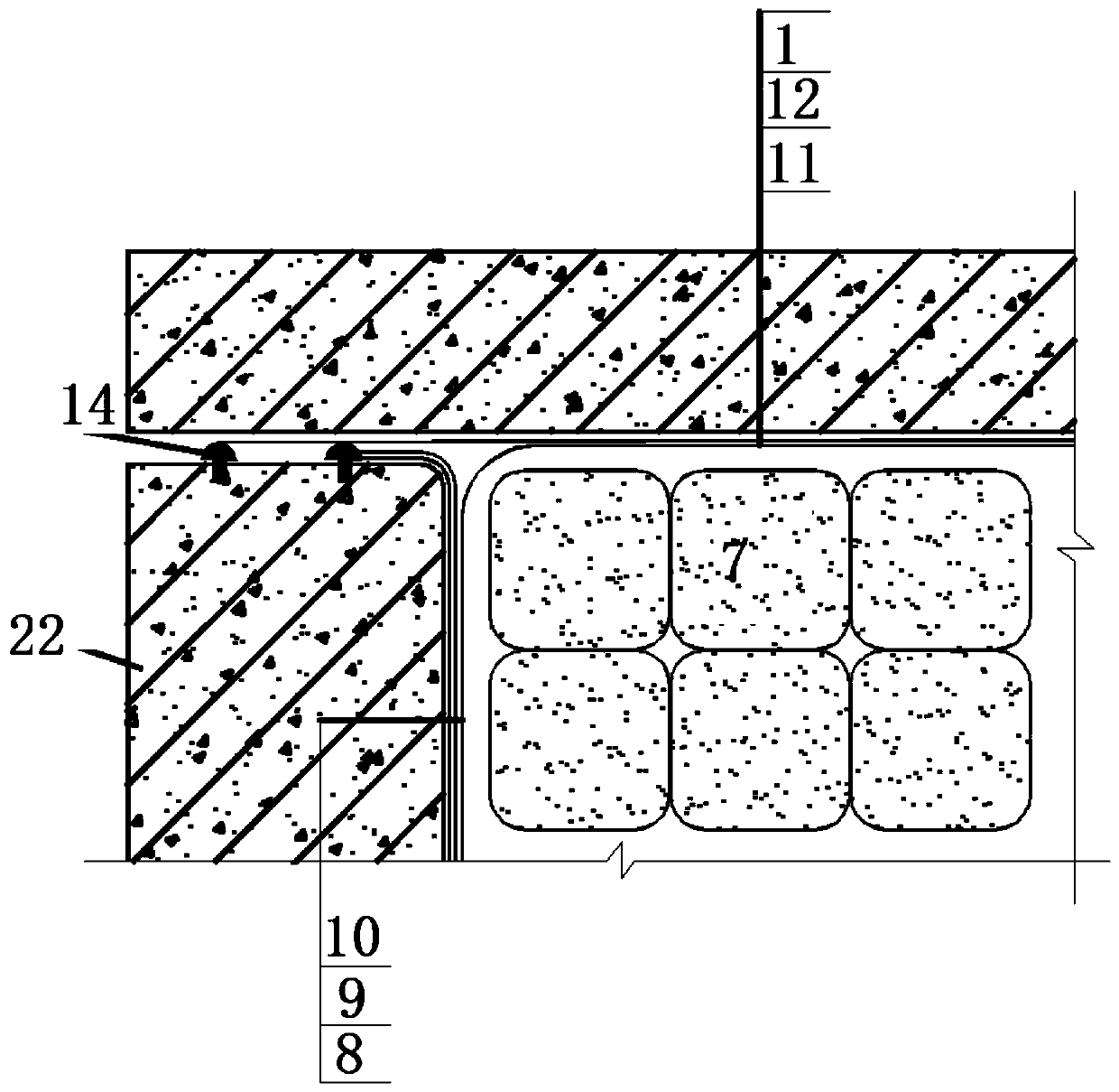
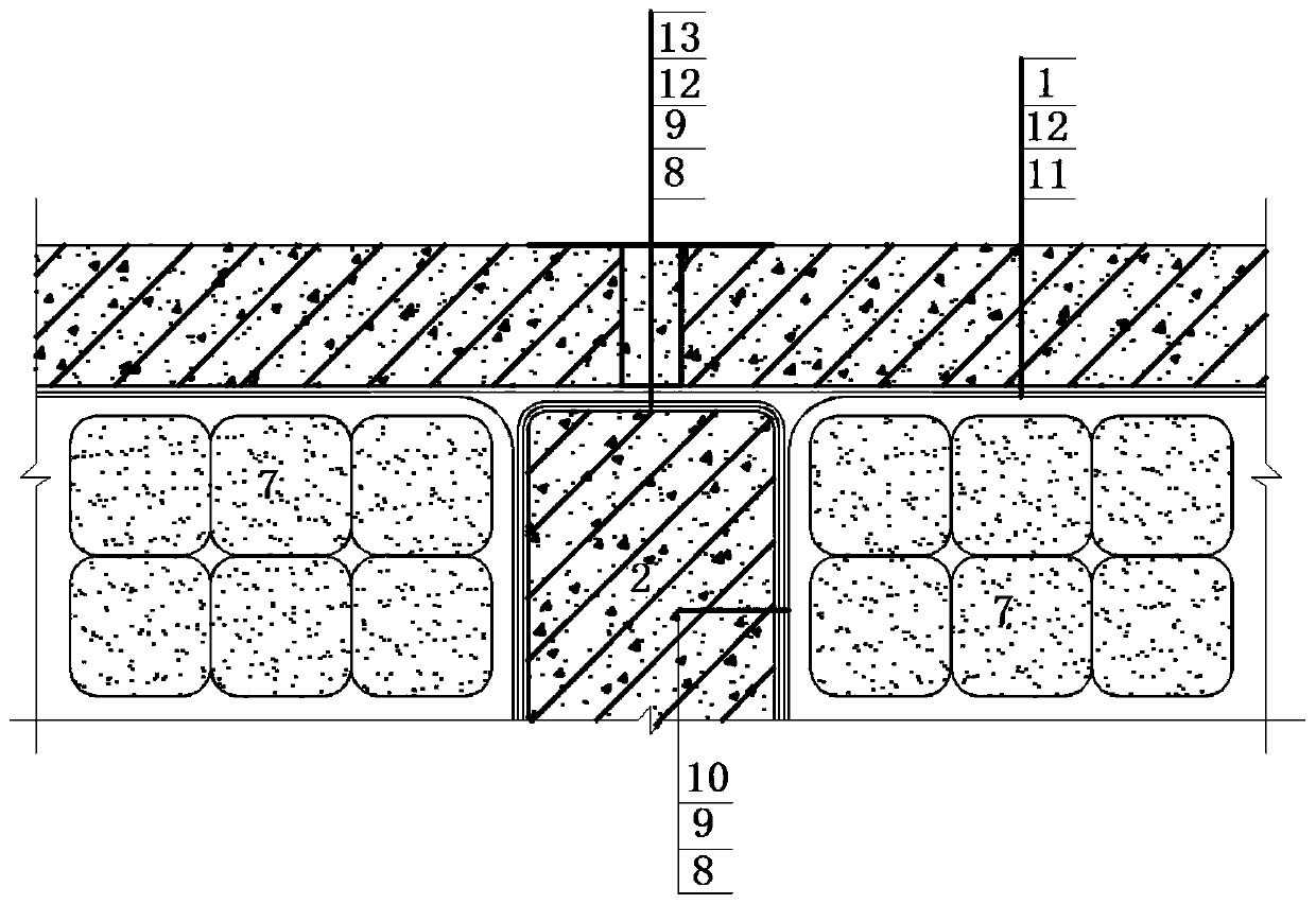
[0043] (1) The anti-seepage structure of rigid landfill in the present invention comprises the flexible anti-seepage structure of reinforced concrete rigid landfill tank structure, inner lining and industrial solid waste or dangerous waste 7 to form, and wherein reinforced concrete rigid landfill tank structure and inner lining The flexible anti-seepage structure and the two together form a five-layer anti-seepage system.

[0044](2)...


PUM


Abstract

The invention discloses a novel rigidity landfill anti-permeation structure and a construction method. The anti-permeation structure comprises a first cavity and a second cavity. The first cavity is formed through closing of a flexible anti-permeation structure, and the flexible anti-permeation structure is located in a closed cavity of a first rigidity anti-permeation structure. The second cavityis located below the first cavity, the second cavity is formed through closing of a second rigidity anti-permeation structure, and the lower surface of the second cavity is coated with an anti-permeation coating. During anti-permeation structure construction, two layers of rigidity anti-permeation structures are formed from bottom to top, and the closed flexible anti-permeation structure is arranged in the upper-layer rigidity anti-permeation structure. Multiple anti-permeation systems are formed by the anti-permeation structure and can effectively prevent environment pollution accidents caused by local structure damage; and through the arrangement of an overhauling observation layer, the abnormal condition of a rigidity landfill can be observed in time, the repairing measure is taken intime for treatment, and abnormal condition enlarging is avoided.

Description

technical field [0001] The invention relates to a novel rigid landfill anti-seepage structure and a construction method, which are suitable for general industrial solid waste and hazardous waste rigid landfill projects. Background technique [0002] Industrial solid waste and hazardous waste carry a large amount of pollutants or will produce a large amount of sewage after being soaked by rainwater. If they are not properly disposed of, they will cause huge pollution to the environment. [0003] At present, landfill disposal technology occupies a considerable proportion in my country's industrial solid waste and hazardous waste disposal technology; industrial solid waste and hazardous waste landfill disposal technology is divided into rigid landfill disposal technology and flexible landfill disposal technology. At present, my country's landfill disposal technology is mainly flexible landfill disposal technology, and as the national environmental protection policy becomes more...

Claims


Application Information

Patent Timeline
Patent Type & Authority Applications(China)
IPC IPC(8): E02D31/00
CPCE02D31/002E02D31/004E02D31/006
Inventor 王河陶维中蒋大基刘军涛吴维兴赵谊梁艳赖建平
Owner CHINA POWER CONSRTUCTION GRP GUIYANG SURVEY & DESIGN INST CO LTD
Why Eureka
Try Eureka