Energy storage and heat pump combined large-temperature-difference cold storage and heat storage system

A heat storage system and large temperature difference technology, applied to heating systems and central heating, can solve the problems of increased system investment, large equipment footprint, and high initial investment of equipment, so as to reduce cooling/heating demand, improve stability, The effect of improving energy efficiency

Inactive Publication Date: 2020-06-05
SOUTHEAST UNIV
View PDF11 Cites 3 Cited by
  • Summary
  • Abstract
  • Description
  • Claims
  • Application Information

AI Technical Summary

Problems solved by technology

[0003] In order to meet the cooling and heating load demand when the air conditioning system is turned on, the cold storage and heat storage system needs to be designed with sufficient cold storage and heat storage capacity, which leads to the large volume of cold storage / heat storage devices, large equipment footprint, and high initial investment of equipment; especially Especially for the air-conditioning system that adopts the full-volume cold storage and heat storage strategy, the large volume of the cold storage / heat storage device doubles the system investment, which greatly reduces the economical efficiency of the cold storage heat storage air conditioning system, and at the same time, the cold storage heat storage efficiency of the device is also low. will be affected

Method used


Image

  • Energy storage and heat pump combined large-temperature-difference cold storage and heat storage system

Examples


Embodiment Construction

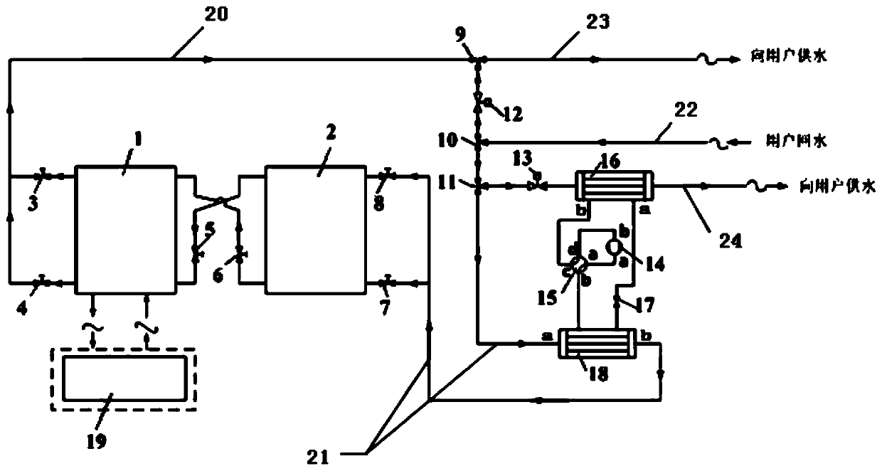
[0024] combined with figure 1 Specific embodiments of the present invention will be further described.

[0025] Such as figure 1In the cold storage and heat storage system shown with a large temperature difference, the first cold / hot water storage tank 1 and the second cold / hot water storage tank 2 are connected by pipelines, and the lower part of the first cold / hot water storage tank 1 The water inlet is connected to the upper water outlet of the second cold storage / hot water storage tank 2, and the third shut-off valve 5 is set on this section of the pipeline; the upper water inlet of the first cold storage / hot water storage tank 1 is connected to the second cold storage / heat storage tank 1 The bottom water outlet of water tank 2, the fourth cut-off valve 6 is set on this section pipeline. The upper and lower water outlets of the first cold storage / hot water storage tank 1 are connected to the first circulation pipeline 20 at the same time, wherein the pipeline at the outl...


PUM


Abstract

The invention relates to an energy storage and heat pump combined large-temperature-difference cold storage and heat storage system. The energy storage and heat pump combined large-temperature-difference cold storage and heat storage system mainly comprises two cold / heat storage water tanks, a cold / heat source supply device, a steam compression type heat pump system, two circulating pipelines, a water return pipeline, a water supply pipeline, stop valves, water mixing valves, flow control valves and the like, wherein the stop valves, the water mixing valves, the flow control valves and the like correspond to the pipelines. According to the energy storage and heat pump combined large-temperature-difference cold storage and heat storage system, the cold / heat storage water tanks are utilizedto store cold / heat generated by the cold / heat source supply device during off-peak electricity, and a large temperature difference is kept between the cold / heat storage temperature and water suppliedto a user, so that the size of the cold / heat storage water tanks is effectively reduced; when the system is used for supplying cold / hot water to the user, the cold / hot water output from the cold / hot water storage tanks is mixed with a part of user return water, supplying to the user is carried out through a first water supply pipeline; and in order to balance the cooling / heating load of the system, a steam compression type heat pump is arranged on a second water supply pipeline and used for performing cooling and heating on the other part of the user return water, so that the requirement of the water supply working condition is met.

Description

technical field [0001] The invention relates to a cold and heat storage device and its cooling / hot water supply method, belonging to the technical field of air conditioning system equipment design and manufacture. Background technique [0002] The development of economy, the expansion of city scale and the change of power consumption structure make the power load difference between city and regional power grid day and night bigger and bigger. The power load of the air-conditioning system is close to about 40% of the total load of the power grid, and the power consumption of the air-conditioner is basically synchronized with the peak and valley of the power grid, which makes the gap between the peak and valley of the power load larger, which brings troubles to the safe, reasonable and economical operation of the power grid. The use of cold storage and heat storage technology to balance the load of the power grid plays a vital role in "shaving peaks and filling valleys" of the...

Claims


Application Information

Patent Timeline
Patent Type & Authority Applications(China)
IPC IPC(8): F24D11/02F24D19/10F24F5/00F24F11/67F24F11/84F24F13/30
CPCF24D11/0214F24D19/1039F24F5/0017F24F13/30F24F11/67F24F11/84F24F2140/20Y02E60/14
Inventor 张伦张小松
Owner SOUTHEAST UNIV
Why Eureka
Try Eureka