
An energy-saving industrial circulating water system and its operation method

A technology of industrial circulating water and circulating water, applied in cooling fluid circulation devices, household refrigeration devices, lighting and heating equipment, etc., can solve the problems of small temperature difference between circulating water supply and return water, energy waste, large output, etc. Losses, the effect of reducing water supply energy consumption and reducing product cost

Active Publication Date: 2021-08-10
上海苏源能源科技有限公司
View PDF8 Cites 0 Cited by
  • Summary
  • Abstract
  • Description
  • Claims
  • Application Information

AI Technical Summary

Problems solved by technology

[0004] The purpose of the present invention is to provide an energy-saving industrial circulating water system and its operation method to solve the problem that the current domestic circulating water system proposed in the above background technology meets or exceeds the maximum output of each unit, the highest variety and specifications, and the highest temperature. Debugging and running under unfavorable conditions, the temperature difference between the circulating water supply and return water is small, which brings a lot of energy waste

Method used


Image

  • An energy-saving industrial circulating water system and its operation method
  • An energy-saving industrial circulating water system and its operation method
  • An energy-saving industrial circulating water system and its operation method

Examples


Embodiment Construction

[0026] The following will clearly and completely describe the technical solutions in the embodiments of the present invention with reference to the accompanying drawings in the embodiments of the present invention. Obviously, the described embodiments are only some of the embodiments of the present invention, not all of them.

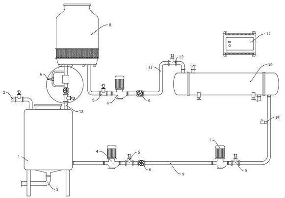
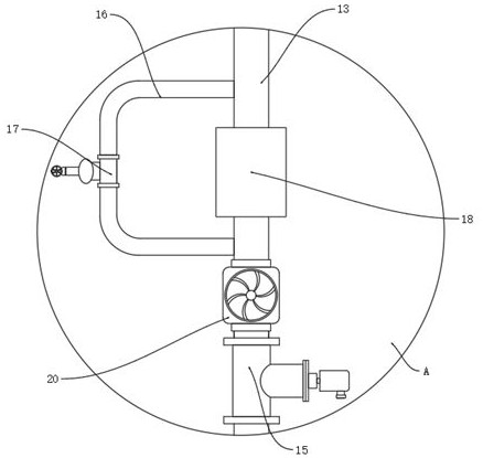
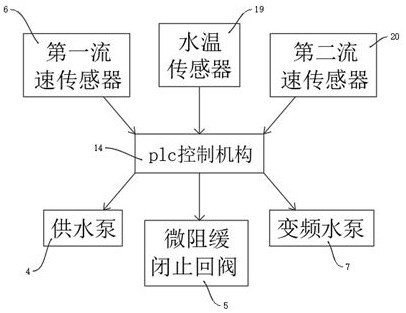
[0027] see Figure 1-3 , an embodiment provided by the present invention: an energy-saving industrial circulating water system, including a water collection tank 1 and a plc control mechanism 14, a water supply pipe 2 is provided above the water collection tank 1, and a sewage discharge pipe is provided below the water collection tank 1 Pipe 3, a cooling tower 8 is arranged on one side of the water collecting tank 1, and the cooling tower 8 and the water collecting tank 1 are sealed and connected by a return pipe 13, and a heat exchanger 10 is arranged on one side of the cooling tower 8, and the heat exchanger 10 The water collecting tank 1 is sealed an...


PUM


Abstract

The invention discloses an energy-saving industrial circulating water system, and relates to the technical field of circulating water systems and their operating methods. In order to solve the most unfavorable conditions of current domestic circulating water systems, such as the maximum output of each unit, the highest variety and specification, and the highest temperature, etc. Conditional commissioning and operation, the temperature difference between the circulating water supply and return water is small, which brings a lot of energy waste. A water supply pipe is provided above the water collecting tank, a sewage discharge pipe is provided below the water collecting tank, a cooling tower is provided on one side of the water collecting tank, and a return pipe passes between the cooling tower and the water collecting tank Sealed connection, a heat exchanger is provided on one side of the cooling tower, and the heat exchanger is sealed with the water collection tank through the outlet pipe of the water collection tank, and the heat exchanger and the cooling tower are connected through a heat exchanger The outlet pipe is sealed and connected, a self-cleaning filter is installed on the return pipe, and a side flow pipe is sealed and installed on one side of the return pipe.

Description

technical field [0001] The invention relates to the technical field of circulating water systems and operating methods thereof, in particular to an energy-saving industrial circulating water system and operating methods thereof. Background technique [0002] Industrial circulating water is mainly used in cooling water systems, so it is also called circulating cooling water. Because industrial cooling water accounts for more than 90% of the total water consumption. There are two types of circulating cooling water: closed type (closed type) and open type. In the closed cooling water system, the cooling water is not exposed to the air, the water loss is very small, and the contents of various minerals and ions in the water generally do not change. In the open circulating water system, the recooling of water is carried out through the cooling tower, so the cooling water must be in contact with the air during the recirculation process, and part of the water will continue to be ...

Claims


Application Information

Patent Timeline
Patent Type & Authority Patents(China)
IPC IPC(8): F25D17/02F25D29/00
CPCF25D17/02F25D29/00
Inventor 郝鹏飞
Owner 上海苏源能源科技有限公司
Learn More