
Dual source constant temperature vacuum drying system

A drying system and vacuum technology, applied in drying, drying machine, drying solid materials, etc., can solve the problems of high energy and cost consumption, high equipment cost, and material loss of taste, etc., to achieve equipment cost reduction, The effect of stabilizing heat supply and improving taste and appearance

Active Publication Date: 2021-04-02
郑州欧纳尔冷暖科技有限公司
View PDF7 Cites 0 Cited by
  • Summary
  • Abstract
  • Description
  • Claims
  • Application Information

AI Technical Summary

Problems solved by technology

Although this kind of vacuum freeze-drying technology has the advantages of low-temperature vacuum drying, it includes a freezing link. The freezing link needs to freeze the material before drying, which will consume a lot of manpower and time. The efficiency is low, and the cost of equipment is high, and Freezing will also cause the material to lose its taste and reduce the quality of the material after drying
[0003] Therefore, it is urgent to improve the existing vacuum drying technology to avoid the loss of nutrients and the change of taste caused by freezing the material and the high consumption of energy and cost

Method used


Image

  • Dual source constant temperature vacuum drying system
  • Dual source constant temperature vacuum drying system
  • Dual source constant temperature vacuum drying system

Examples


Embodiment Construction

[0023] In order to make the purpose, technical solution and advantages of the present invention clearer, the technical solution of the present invention will be described in detail below. Apparently, the described embodiments are only some of the embodiments of the present invention, but not all of them. Based on the embodiments of the present invention, all other implementations obtained by persons of ordinary skill in the art without making creative efforts fall within the protection scope of the present invention.

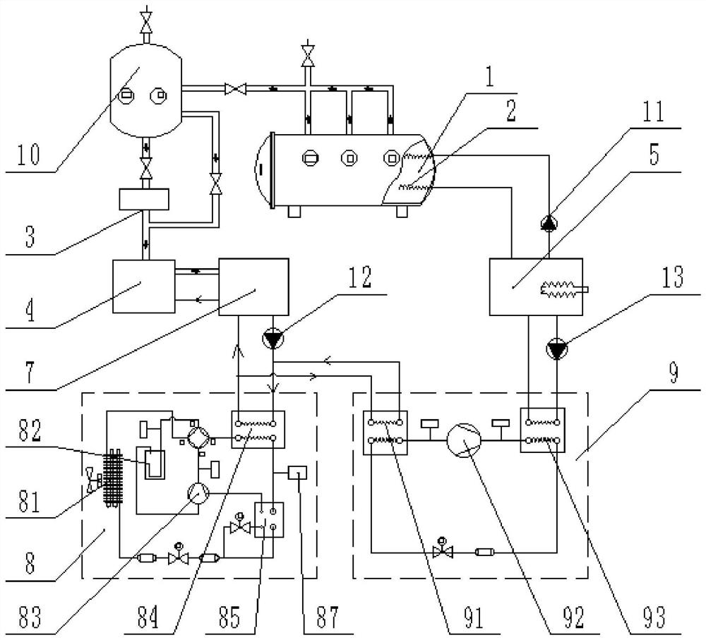
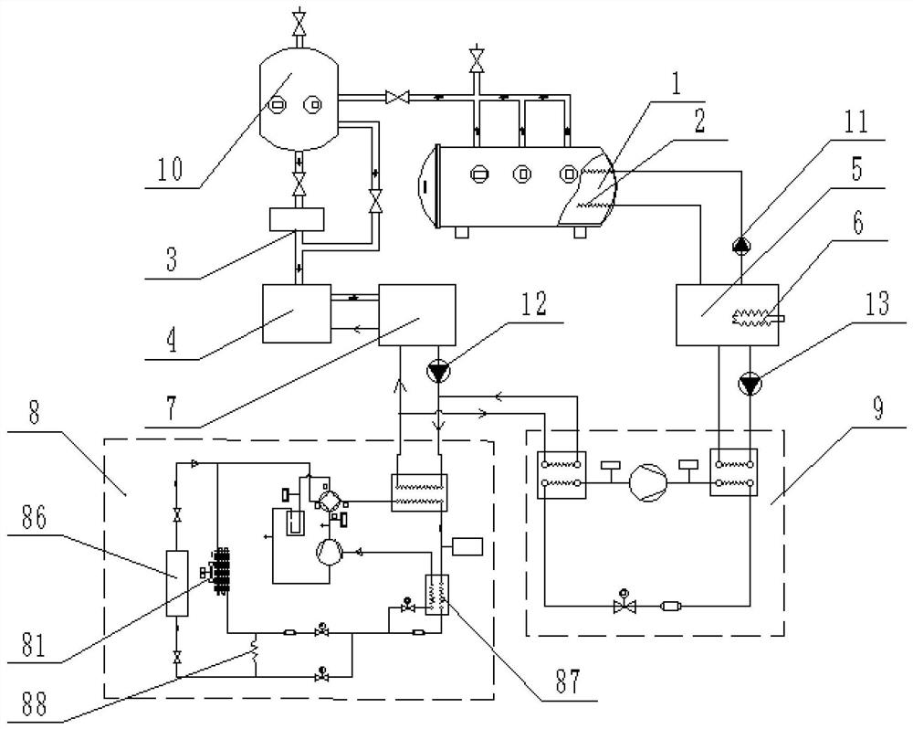
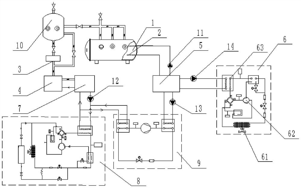
[0024] The purpose of this specific embodiment is to provide a dual-source constant temperature vacuum drying system, which has two heat sources to supply heat to the vacuum drying chamber, so that the material is dried under low-temperature vacuum, avoiding the freezing process, and effectively saving energy; and One of the heat sources is the waste heat recovery and utilization of the pump unit air, which further reduces energy consumption; the two heat source...


PUM


Abstract

The invention discloses a double-source constant-temperature vacuum drying system. The system comprises a vacuum drying unit, a heat supply assembly, a waste heat recovery unit and a control assembly,wherein the vacuum drying unit is provided with a vacuum drying bin, and a heat exchanger and a water ring pump which are arranged in the vacuum drying bin; the heat supply assembly is provided witha high-temperature water tank and a first auxiliary heater, and the high-temperature water tank communicates with a medium inlet and a medium outlet of the heat exchanger; the waste heat recovery unitis provided with a low-temperature water tank, a second auxiliary heater and a water source heat pump, the low-temperature water tank communicates with a water inlet and a water outlet of the water ring pump and a heat exchanging inlet and a heat exchanging outlet of a first evaporator of the water source heat pump, and the high-temperature water tank communicates with a heat exchanging inlet anda heat exchanging outlet of a first condenser of the water source heat pump; and the control assembly is provided with a controller, a first temperature sensor used for detecting the temperature in the vacuum drying bin, a second temperature sensor used for detecting the temperature of water in the high-temperature water tank, and a third temperature sensor used for detecting the temperature in the low-temperature water tank. Materials are subjected to constant-temperature heating drying in low-temperature vacuum, energy is saved, and damage to nutrients and tastes of the materials is reduced.

Description

technical field [0001] The invention relates to the technical field of vacuum drying, and more specifically relates to a dual-source constant temperature vacuum drying system. Background technique [0002] At present, vacuum drying technology has appeared in the field of material drying technology. Vacuum drying refers to pre-freezing the material, then putting the material into the drying bin under freezing conditions, and then vacuuming the drying bin to directly sublimate the moisture of the material and remove it. With the gas being pumped away, the material is dried. Although this kind of vacuum freeze-drying technology has the advantages of low-temperature vacuum drying, it includes a freezing link. The freezing link needs to freeze the material before drying, which will consume a lot of manpower and time. The efficiency is low, and the cost of equipment is high, and Freezing will also cause the material to lose its taste and reduce the quality of the dried material. ...

Claims


Application Information

Patent Timeline
Patent Type & Authority Patents(China)
IPC IPC(8): F26B9/06F26B5/04F26B23/10F26B25/00
CPCF26B5/04F26B9/06F26B23/10F26B25/00Y02P70/10
Inventor 苟秋平牛书霞
Owner 郑州欧纳尔冷暖科技有限公司
Learn More