Dynamic and static combined loading rock fracture characterization test device and method matched with industrial CT machine

A dynamic and static combined loading and test device technology, applied in the field of geotechnical mechanics, can solve the problem of inability to observe the rock fracture evolution process in real time, and achieve the effect of improving the attenuation of ray energy, high strength and low density

Pending Publication Date: 2020-06-05
UNIV OF SCI & TECH BEIJING
9 Cites 13 Cited by

AI-Extracted Technical Summary

Problems solved by technology

[0003] The macroscopic deformation and failure mechanism of rocks under stress can be obtained through triaxial tests, but triaxial tes...

Method used

S15: analyze gained test data, obtain the crack evolution (such as crack width, length, spatial position) process of rock deformation failure process under static and dynamic combined load, carry out three-dimensional reconstruction, damage evolution description and damage variable to sample crack Realize the visualization and digital representation of the rock fracture process under dynamic and static combined stress disturbance.
[0048] The pressure chamber adopts special materials, which have the advantages of high strength and low density, such as carbon fiber, which improves the energy attenuation of X-rays when they pass through the pressure chamber while meeting the functional requirements. There are flanges at both ends of the pressure chamber, which are used to connect with the connecting plate of the lower cover of the upper oil cylinder and the upper cover of the lower oil ...

Abstract

The invention provides a dynamic and static combined loading rock fracture characterization test device and method matched with an industrial CT machine, and belongs to the technical field of geotechnical mechanics. The test device comprises an axial pressure system, a confining pressure system, a rotating system and a scanning system; the axial pressure system realizes axial dynamic and static combined stress disturbance loading on a sample, the confining pressure system applies confining pressure to the sample, the rotating system drives the testing machine to rotate through a turntable, andthe scanning system obtains an absorption coefficient of a scanned object through a series of scanning at different angles and performs three-dimensional imaging. According to the invention, the industrial CT scanning technology is utilized, the mesoscopic damage and dynamic fracture evolution process of the rock under dynamic and static combined stress disturbance is observed in real time, and the fracture evolution process of the rock is visually and digitally characterized. The pressure chamber is made of carbon fibers made of special materials and has the advantages of being high in strength and small in density, the ray energy attenuation condition when X-rays penetrate through the pressure chamber is improved under the condition that the function requirement is met, and the triaxialcylinder wall of the pressure chamber bears loading counter-acting force.

Application Domain

Technology Topic

Image

  • Dynamic and static combined loading rock fracture characterization test device and method matched with industrial CT machine
  • Dynamic and static combined loading rock fracture characterization test device and method matched with industrial CT machine
  • Dynamic and static combined loading rock fracture characterization test device and method matched with industrial CT machine

Examples

  • Experimental program(1)

Example Embodiment

[0037] In order to make the technical problems, technical solutions and advantages to be solved by the present invention clearer, a detailed description will be given below in conjunction with the accompanying drawings and specific embodiments.
[0038] The invention provides an industrial CT machine supporting dynamic and static combined loading rock fracture characterization test device and method.
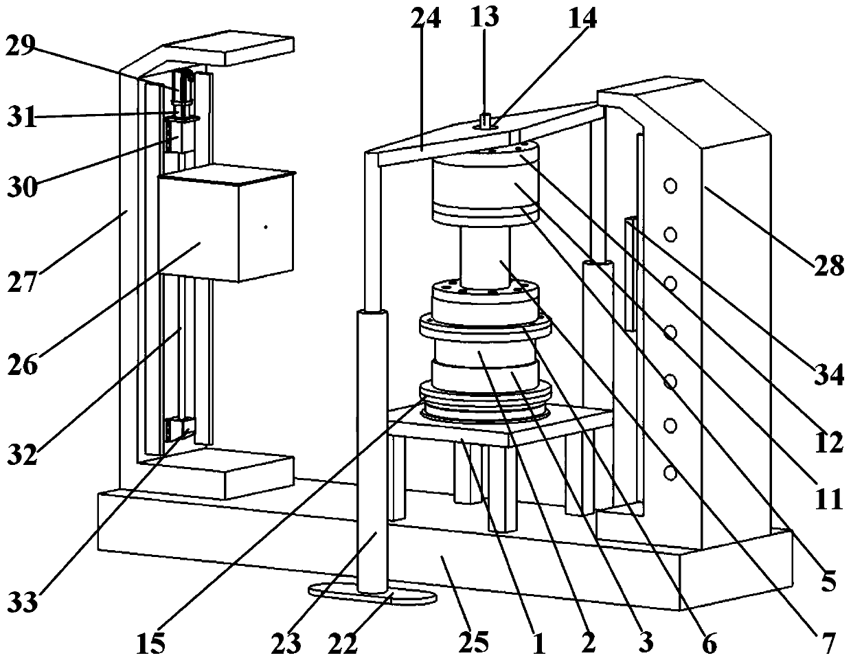
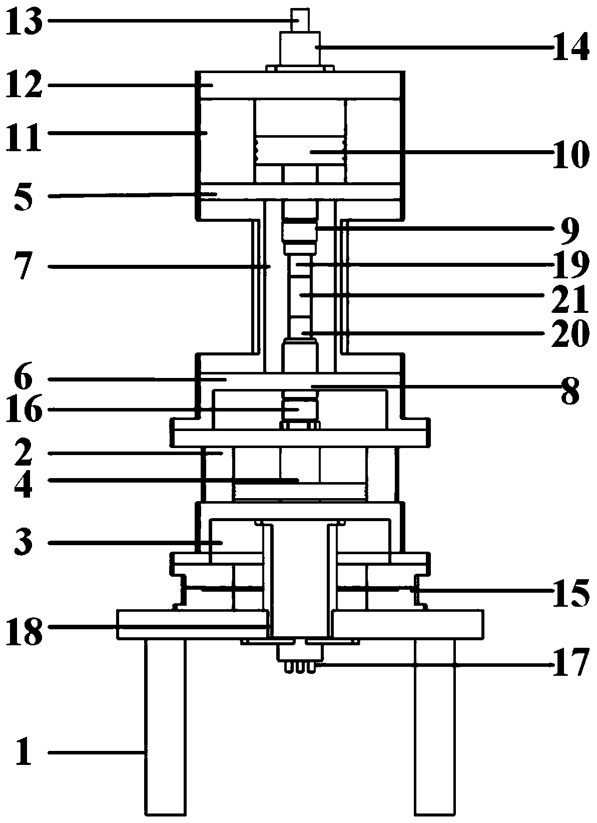
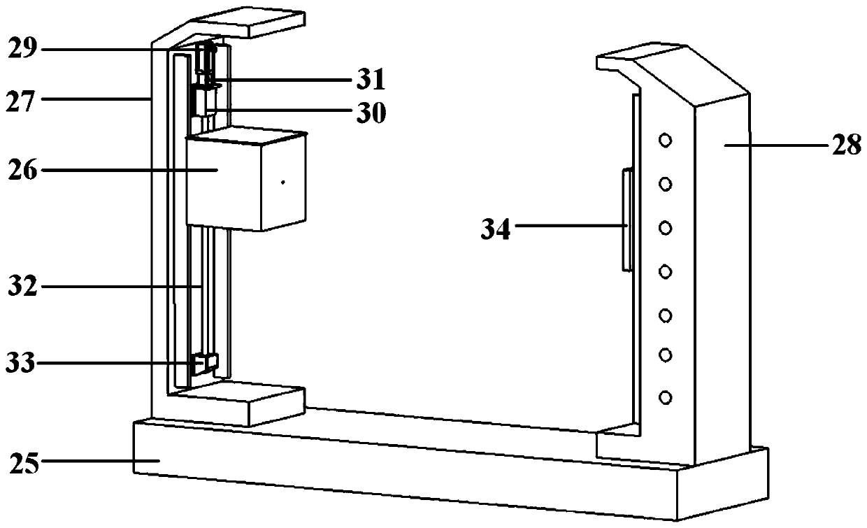
[0039] Such as figure 1 with figure 2 As shown, the device includes a testing machine base 1, an axial compression system, a confining pressure system, a rotation system, and a scanning system. The axial compression system includes an upper cylinder rigid body 11, an upper cylinder upper cover 12, an upper cylinder lower cover connecting plate 5, and an upper cylinder Piston 10, lower cylinder cover 3, lower cylinder upper cover connecting plate 6, lower cylinder barrel 2, lower cylinder rigid body and lower cylinder piston 4. The confining pressure system includes pressure chamber 7, built-in pressure sensor 9, external pressure sensor 16, Upper pressure head 19, lower pressure head 20, lifting cylinder lifting rod 23, lifting cylinder base 22 and lifting cylinder beam 24, the rotating system includes turntable 15, upper rotating slip ring stator 13, upper rotating slip ring rotor 14, lower rotating slip ring The stator 17 and the lower rotating slip ring rotor 18, the scanning system includes X-ray transmitter 26, X-ray detector 34, transmission motor 29, transmission reducer 31, transmission motor seat 30, transmission bearing seat 33, transmission screw 32, pad Iron 25 and vertical frame.
[0040] The turntable 15 is placed on the base 1 of the testing machine and is connected by the lower rotating slip ring stator 17 and the lower rotating slip ring rotor 18. The upper part of the turntable 15 is connected with the lower cylinder cover 3, and the lower cylinder cover 3 is placed under the lower cylinder barrel 2. The upper part of the lower cylinder barrel 2 is placed on the lower cylinder upper cover connecting plate 6, the upper part of the lower cylinder upper cover connecting plate 6 is the pressure chamber 7, and the lower part of the pressure chamber 7 is provided with a lower pressure head 20, and the upper pressure head 19 is correspondingly set above the lower pressure head 20. The upper cylinder rigid body 11 is arranged above the chamber 7, the lower part of the upper cylinder rigid body 11 is the upper cylinder lower cover connecting plate 5, the upper part of the upper cylinder rigid body 11 is the upper cylinder upper cover 12, and the upper cylinder upper cover 12 is provided with the upper rotating slip ring rotor 14 and the upper Rotating slip ring stator 13.
[0041] A lower cylinder piston 4 is arranged in the lower part of the lower cylinder barrel 2, a pressure chamber piston 8 is arranged at the upper part, and an upper cylinder piston 10 is arranged in the upper cylinder rigid body 11.
[0042] An external pressure sensor 16 is installed outside the lower cylinder tube 2, such as Figure 4 As shown, a built-in pressure sensor 9 is provided above the inside of the pressure chamber 7.
[0043] A sample 21 is placed between the upper indenter 19 and the lower indenter 20.
[0044] Such as Figure 5 As shown, the lifting cylinder base 22 is connected to the lifting cylinder beam 24 through the lifting cylinder lifting rod 23, which straddles the testing machine base 1 with a hole in the middle of the lifting cylinder beam 24, and the upper rotating slip ring rotor 14 is installed in the hole.
[0045] Such as figure 1 with image 3 As shown, the base 1 of the testing machine is placed on the horn 25. There is a vertical frame at each end of the horn 25, which is the vertical frame one 27 and the vertical frame two 28. The X-ray transmitter 26 passes through the transmission The screw 32 is installed on the vertical frame one 27, the X-ray detector 34 is installed on the vertical frame two 28, and the vertical frame one 27 is provided with a transmission motor 29. The transmission motor 29 is installed on the vertical frame 27 through a transmission reducer 31. On the transmission motor base 30, the lower part of the transmission screw 32 is connected to the transmission bearing base 33.
[0046] The pressure chamber 7 is made of carbon fiber, and both ends of the pressure chamber 7 are provided with flanges for connecting with the upper cylinder lower cover connecting plate 5 and the lower cylinder upper cover connecting plate 6.
[0047] In the specific design, the lower cylinder piston is hollow, which is used to pass the signal line in the pressure chamber and the confining oil to the rotor of the rotating slip ring. The upper oil cylinder and the lower oil cylinder rely on the driving force of the pump to make the hydraulic oil enter the oil cylinder through the hydraulic pipeline, and realize the axial dynamic and static combined stress disturbance loading for the prepared samples. When loading, the lower cylinder first applies pressure to the sample to simulate the vertical static stress of the rock, then the confining pressure is applied to simulate the static stress, and then the upper cylinder applies disturbance stress to the sample. The waveform of the disturbance load has many forms: cosine wave, triangle wave, square wave, etc. The amplitude of the applied disturbance force is divided into displacement and load. The test can realize the loading of different strain rates by adjusting the loading frequency, and adjusting the amplitude to achieve different Simulation of dynamic disturbance amplitude. The entire loading device is placed on a turntable and rotated by a rotating system, and the reaction force when loading the sample is all borne by the three-axis cylinder wall of the pressure chamber.
[0048] The pressure chamber adopts special materials, which have the advantages of high strength and low density, such as carbon fiber, which improves the attenuation of X-ray energy when X-rays pass through the pressure chamber while meeting functional requirements. There are flanges at both ends of the pressure chamber, which are used to connect the upper cylinder lower cover connecting plate and the lower cylinder upper cover connecting plate. The lifting cylinder is used to lift the test machine and provide counterforce for the upper slip ring. After the sample is prepared, start the lifting cylinder, the lifting cylinder lifting rod drives the pressure chamber and the upper structure to rise, when the sample is installed, the lifting cylinder lifting rod goes down. The bottom of the pressure chamber is connected with the turntable through a bottom connecting piece, so that the pressure chamber and the turntable are connected stably during operation. The application of the confining pressure is to fill the pressure chamber with nitrogen through the reserved air duct. First, open the booster control valve, and the nitrogen in the booster is filled into the pressure chamber along the reserved air duct to apply confining pressure to the sample.
[0049] The upper part of the turntable is connected with the lower cover of the lower cylinder for driving the rotation of the testing machine, and the lower part of the turntable is connected with the base of the testing machine. The upper rotating slip ring is a liquid supply. The slip ring has two hydraulic circuits for supplying oil to the upper cylinder. The stator of the upper rotating slip ring is connected to the beam of the lifting cylinder and does not rotate with the testing machine. The upper rotating slip ring rotor is connected to the upper end of the upper cylinder. The cover is connected and rotates synchronously with the testing machine when working. The lower rotating slip ring is a multi-channel fluid supply and power supply slip ring, used for the confining pressure supply of the lower cylinder and pressure chamber, as well as the transmission of the deformation sensor in the pressure chamber, the built-in pressure sensor and even the acoustic emission signal. The lower rotating slip ring rotor and the lower cylinder The lower cover is connected and rotates with the testing machine, and the lower rotating slip ring stator is connected with the base of the testing machine and does not rotate with the testing machine.
[0050] The X-ray transmitter emits X-rays, the X-rays pass through the scanned object, and some of the rays are absorbed by the scanned object, and the transmitted rays are received by the detector. Through a series of scanning at different angles, the absorption coefficient of the scanned object is obtained and three-dimensional imaging is performed. Through the analysis of the original fabric of the rock under the dynamic and static combined stress disturbance, the structure after fracture, especially the internal structure evolution law during the deformation and fracture process, the microscopic mechanism of the rock macromechanical behavior is revealed.
[0051] The method of applying the device includes the following steps:
[0052] S1: Preparation The rock sample of the sample is wrapped in a transparent plastic tube for testing;
[0053] S2: Start the lifting cylinder, the lifting cylinder lift rod drives the pressure chamber and the upper structure to rise, and then install the sample. After the sample is installed, the lifting cylinder lift rod will drop and be firmly connected to the turntable through the bottom connector. In this process, it is necessary to ensure that the axis of the sample is aligned with the axis of the upper and lower indenters of the pressure chamber;
[0054] S3: Check the upper device of the turntable and make sure it is well fixed;
[0055] S4: Turn on the main power supply of the power distribution cabinet, and the power indicator is on, indicating that the main power supply is working normally. Power on each sub-system: turn on the power of each sub-system in turn, the X-ray machine control box is powered on, and the detector and data acquisition sub-system, trigger module, scanning control sub-system, camera monitoring equipment, etc. are all powered;
[0056] S5: Start the X-ray machine, select the preheating mode and preheat according to the length of time since the last shutdown. At the same time, start the computer system and run the corresponding software to establish a connection via Ethernet;
[0057] S6: Set rock sample information, select or modify scan parameters (such as scan height range, turntable speed, lifting speed, translation speed, step length, micro-motion parameters, etc.) on the computer system control station;
[0058] S7: Scanning starts. The X-ray machine emits the beam, the detector receives the signal, the scanning device subsystem completes the required various movements, and the scanning control subsystem performs real-time control. The initial state of the rock can be scanned at the beginning;
[0059] S8: Open the supercharger control valve, the nitrogen in the supercharger is filled into the pressure chamber along the reserved air duct, and the confining pressure is applied to the sample. When the confining pressure reaches the pressure value set in the test, the supercharger is closed Control valve
[0060] S9: Start the testing machine, rotate it at a certain speed, and deliver oil to the upper and lower cylinders to apply dynamic load to the sample. First, the lower cylinder applies pressure to the sample to simulate the vertical static stress of the rock, then the confining pressure is applied to simulate the static stress, and then the upper cylinder applies disturbance stress to the sample. The waveform of the disturbance load has many forms: cosine wave, triangle wave, square wave, etc. The amplitude of the applied disturbance force is divided into displacement and load. The test can realize the loading of different strain rates by adjusting the loading frequency, and adjusting the amplitude to achieve different Simulation of dynamic disturbance amplitude. During scanning, adjust the oil pressure of the upper and lower cylinders to change the loading of the sample, so as to achieve the combined dynamic and static stress disturbance of the sample.
[0061] S10: Scanning at different stages when the rock is disturbed by fatigue. During CT scan imaging, the mechanical loading test must be stopped. During each stage of scanning, the X-ray machine emits beams, the detector receives signals, and the scanning device sub-system completes the required movements. The scanning control sub-system performs real-time control to obtain CT images of different stages; at the end of each scan, the X-ray machine stops When the beam is released, the equipment of the scanning device sub-system stops moving;
[0062] S11: Check the obtained CT image. When a suspicious defect is found on the image, locate the height of the defect on the image, and perform CT scan reconstruction at the designated detection height or perform another experiment;
[0063] S12: Turn off the radiation source of the CT machine, unload the pressure chamber, remove the sample, and end the test;
[0064] S13: The above S2-S12 is a CT scan test under a combined dynamic and static cycle loading condition. Repeat S2-S12 for multiple tests;
[0065] S14: After all inspection tasks are completed, after waiting for the X-ray machine to dissipate heat, turn off the power of the X-ray machine, turn off the power of the computer and the numerical control system, disconnect the switches of each sub-system, and disconnect the main power of the system;
[0066] S15: Analyze the obtained test data, obtain the crack evolution (such as crack width, length, spatial position) of the rock under combined dynamic and static loads, and perform 3D reconstruction, damage evolution description, and damage variable analysis of the sample cracks. Visual and digital characterization of rock failure process under combined dynamic and static stress disturbance.
[0067] The above are the preferred embodiments of the present invention. It should be pointed out that for those of ordinary skill in the art, without departing from the principle of the present invention, several improvements and modifications can be made. These improvements and modifications It should also be regarded as the protection scope of the present invention.

PUM

no PUM

Description & Claims & Application Information

We can also present the details of the Description, Claims and Application information to help users get a comprehensive understanding of the technical details of the patent, such as background art, summary of invention, brief description of drawings, description of embodiments, and other original content. On the other hand, users can also determine the specific scope of protection of the technology through the list of claims; as well as understand the changes in the life cycle of the technology with the presentation of the patent timeline. Login to view more.

Similar technology patents

Classification and recommendation of technical efficacy words

  • High strength
  • Low density

Nitride semiconductor laser device

ActiveUS20090141765A1Improve life characteristicsLow densityOptical wave guidanceLaser detailsElectron blocking layerLaser
Owner:ROHM CO LTD
Why Eureka
Try Eureka