Planar miniature multi-channel fluorescence detection optical system
What is AI technical title?
AI technical title is built by Patsnap AI team. It summarizes the technical point description of the patent document.
A fluorescence detection and optical system technology, applied in the field of multi-channel fluorescence detection, can solve the problems of use, poor placement, and poor installation of optical components.
Pending Publication Date: 2020-06-05
SUZHOU MOLARRAY CO LTD
View PDF0 Cites 18 Cited by
Summary
Abstract
Description
Claims
Application Information
AI Technical Summary
This helps you quickly interpret patents by identifying the three key elements:
Problems solved by technology
Method used
Benefits of technology
Problems solved by technology
[0005] The technical solution of the present invention is: a planar miniature multi-channel fluorescence detection optical system, which can be applied to fluorescence quantitative PCR, portable PCR, fast PCR, etc., and solves the problem that the traditional fluorescence detection optical system is bulky and the three-dimensional type is not good in equipment. Placement, the problem of poor installation of optical components
At the same time, it also solves the problem that the traditional multi-channel fluorescence detection optical system needs to use a mechanical turntable.
Method used
Image
Click on the blue label to locate the original text in one second.
Reading with bidirectional positioning of images and text.
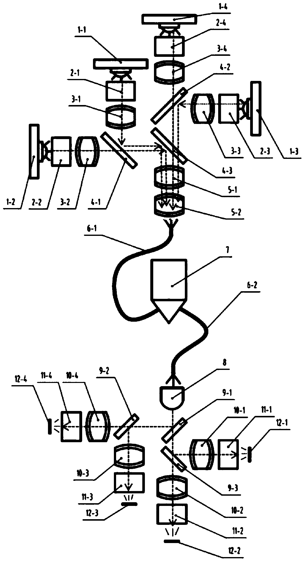
[0032] Such as figure 1 As shown, the planar lighting assembly includes: a cylindrical lens (8), a lighting dichroic mirror (9-1, 9-2, 9-3), a lighting focusing lens (10-1, 10-2, 10-3 , 10-4), daylighting filters (11-1, 11-2, 11-3, 11-4), photoelectric sensors (12-1, 12-2, 12-3, 12-4).
[0033] Such as figure 1 As shown, a reaction cell (7) is included between the planar excitation light assembly and the planar lighting assembly, the reaction cell (7) is connected to the planar excitation light assembly through the incident optical fiber (6-1), and the reaction cell (7) passes through the exit The optical fiber (6-2) is connected to the planar lighting assembly.
[0034] ...
Embodiment 2
[0042] In this solution, excitation light dichroic mirrors (4-1, 4-2, 4-3) and lighting dichroic mirrors (9-1, 9-2, 9-3) are included.
[0043] Specifically, the transmission and reflection bands of each dichroic mirror are:
[0044] The specifications of the excitation light dichroic mirror (4-1) are: 400nm-485nm reflection, 500nm-700nm transmission;
[0045] The specifications of the excitation light dichroic mirror (4-2) are: 500nm-590nm reflection, 600nm-700nm transmission;
[0046] The specifications of the excitation light dichroic mirror (4-3) are: 400nm-550nm reflection, 560nm-700nm transmission;
[0047] The specifications of the lighting dichroic mirror (9-1) are: 450nm-580nm transmission, 600nm-750nm reflection;
[0048] The specifications of the lighting dichroic mirror (9-2) are: 500nm-630nm reflection, 650nm-700nm transmission;
[0049] The specifications of the lighting dichroic mirror (9-3) are: 400-535nm reflection, 550nm-700nm transmission;
[0050] Based...
PUM
Abstract
The invention discloses a planar miniature multi-channel fluorescence detection optical system which comprises a planar exciting light assembly and a planar lighting assembly; the reaction tank is respectively connected to said two assemblies through optical fibers; the planar exciting light assembly includes that single LED light source light serves as single-channel light to penetrate through adichroscope after being filtered and collimated and / or is focused to an optical fiber after being reflected by the dichroscope; the single-channel light in different directions passes through the first-stage dichroscope and then is output as a group of light beams in the same emitting direction; the light beams in different directions pass through a second-stage dichroscope and then are output asa multi-channel light beam group in the same emitting direction; the planar lighting assembly is characterized in that a fluorescence reaction passes through a cylindrical lens and then penetrates through a dichroscope and / or is reflected by the dichroscope and then is separated into a plurality of single-channel fluorescence in different directions, and the single-channel fluorescence is focusedand filtered and then is transmitted to a photosensitive surface of a photodiode; the fluorescence in the single direction passes through a second-stage dichroscope and then is output as fluorescencebeams in different emitting directions; and each group of fluorescence beams pass through the first-stage dichroscope and then are output as single-channel fluorescence in different emitting directions.
Description
technical field [0001] The invention relates to the technical field of multi-channel fluorescence detection, in particular to a planar miniature multi-channel fluorescence detection optical system. Background technique [0002] Fluorescence detection is a natural luminescent reaction. Through the reaction of luciferase and ATP, it can detect human cells, bacteria, mold, and food residues, and the reaction results can be obtained within 15 seconds. Fluorescenceilluminance is generally measured by light-sensing equipment and expressed in digital form. [0003] At present, fluorescence detection is the most widely used fluorescent quantitative PCR technology, which refers to the method of adding fluorescent groups to the PCR reaction system, realizing the real-time monitoring of the whole process of PCR through the continuous accumulation of fluorescent signals, and then quantitatively analyzing the unknown template through the standard curve. . [0004] Usually, in fluoresc...
Claims
Application Information
Patent Timeline
Application Date:The date an application was filed.
Publication Date:The date a patent or application was officially published.
First Publication Date:The earliest publication date of a patent with the same application number.
Issue Date:Publication date of the patent grant document.
PCT Entry Date:The Entry date of PCT National Phase.
Estimated Expiry Date:The statutory expiry date of a patent right according to the Patent Law, and it is the longest term of protection that the patent right can achieve without the termination of the patent right due to other reasons(Term extension factor has been taken into account ).
Invalid Date:Actual expiry date is based on effective date or publication date of legal transaction data of invalid patent.

