
Multifunctional power equipment

A kind of power equipment and multi-functional technology, which is applied in the direction of electrical components, circuit devices, emergency protection circuit devices for limiting overcurrent/overvoltage, etc. It can solve the problem that the equipment does not have the function of installation and fixing adjustment, and the terminals are easily affected by dust , Unable to adjust the installation and other problems, to achieve the effect of ensuring the tightness of the connection and protection, good protection and shielding effect, and avoiding the influence of dust

Inactive Publication Date: 2020-06-05
彭沙沙
View PDF0 Cites 4 Cited by
  • Summary
  • Abstract
  • Description
  • Claims
  • Application Information

AI Technical Summary

Problems solved by technology

[0006] In order to solve the above-mentioned technical problems, the present invention provides multifunctional power equipment to solve the problem that the existing power equipment does not have the installation and fixing adjustment function outside the equipment, the outdoor power supply operation is easily affected by the weather, and the connecting terminals are easily affected by exposure to air. Problems of dust influence and inability to adjust the position where electrical equipment is installed

Method used


Image

  • Multifunctional power equipment
  • Multifunctional power equipment
  • Multifunctional power equipment

Examples


Embodiment Construction

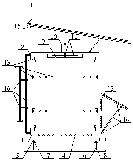
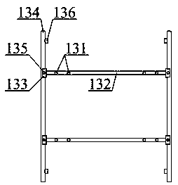
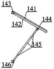
[0034] Below in conjunction with accompanying drawing, the present invention is described in detail, as shown in accompanying drawing 1 and accompanying drawing 2, multifunctional electric equipment, comprises electric cabinet cabinet door 1, hinge 2, electric equipment installation cabinet 3, ventilation net 4, fixed cover Tube 5, support rod 6, thumb screw 7, support base 8, hollow wind cover 9, heat dissipation motor 10, fan blade 11, connection terminal 12 for incoming and outgoing lines, adjustable mounting plate structure 13 for power equipment with different adaptability, and the connection terminal can be Adjust the protective shutter structure 14, install the lightning protection rain shield structure 15 and the adjustable fixed installation bracket structure 16 outdoors, and the longitudinal left end of the power cabinet door 1 is installed in front of the power equipment installation cabinet 3 through the hinge 2 The left end of the part; the power cabinet door 1 and...


PUM


Abstract

The invention provides multifunctional power equipment. The multifunctional power equipment comprises a power cabinet door, hinges, a power equipment mounting cabinet, a ventilation net, a fixing sleeve, a supporting rod, a wing-shaped screw, a supporting base, a hollow fan cover, a heat dissipation motor, fan blades, an incoming and outgoing line wiring terminal and a power equipment adjustable mounting plate structure with different adaptability. According to the invention, power equipment mounting holes, mounting plates for different power equipment, a U-shaped adjusting sliding block, a linear sliding rail, a square head bolt and a stop block are arranged; different types of power equipment can be fixedly mounted; the installation requirements of different power equipment are met; proper power equipment mounting holes are selected for mounting and fixing according to the model of the power equipment; meanwhile, the square-head bolt is loosened, and the position of the U-shaped adjusting sliding block on the outer wall of the linear sliding rail is adjusted to determine the distance between different power equipment mounting plates; the square-head bolt is locked, and then powerequipment mounting and fixing work can be conducted; the stopping effect can be achieved through the stop block; and the adjusting safety is guaranteed.

Description

technical field [0001] The invention belongs to the technical field of electric equipment, and in particular relates to multifunctional electric equipment. Background technique [0002] Electricity is an energy source powered by electrical energy. The large-scale power system that appeared in the 20th century is one of the most important achievements in the history of human engineering science. It is a power production and consumption system composed of power generation, power transmission, power transformation, power distribution and power consumption. It converts the primary energy of nature into electricity through mechanical energy devices, and then supplies electricity to various users through power transmission, transformation and distribution. Power equipment mainly includes two categories: power generation equipment and power supply equipment. Power generation equipment is mainly power plant boilers, steam turbines, gas turbines, water turbines, generators, transfor...

Claims


Application Information

Patent Timeline
Patent Type & Authority Applications(China)
IPC IPC(8): H02B1/30H02B1/28H02B1/56H02B1/14H02H9/06
CPCH02B1/14H02B1/28H02B1/30H02B1/565H02H9/06
Inventor 彭沙沙
Owner 彭沙沙
Learn More