Linearized energetic radio-frequency plasma ion source
A plasma and ion source technology, applied in the field of generating gas discharge, can solve impractical problems
- Summary
- Abstract
- Description
- Claims
- Application Information
AI Technical Summary
Problems solved by technology
Method used
Image

Examples
Embodiment 1
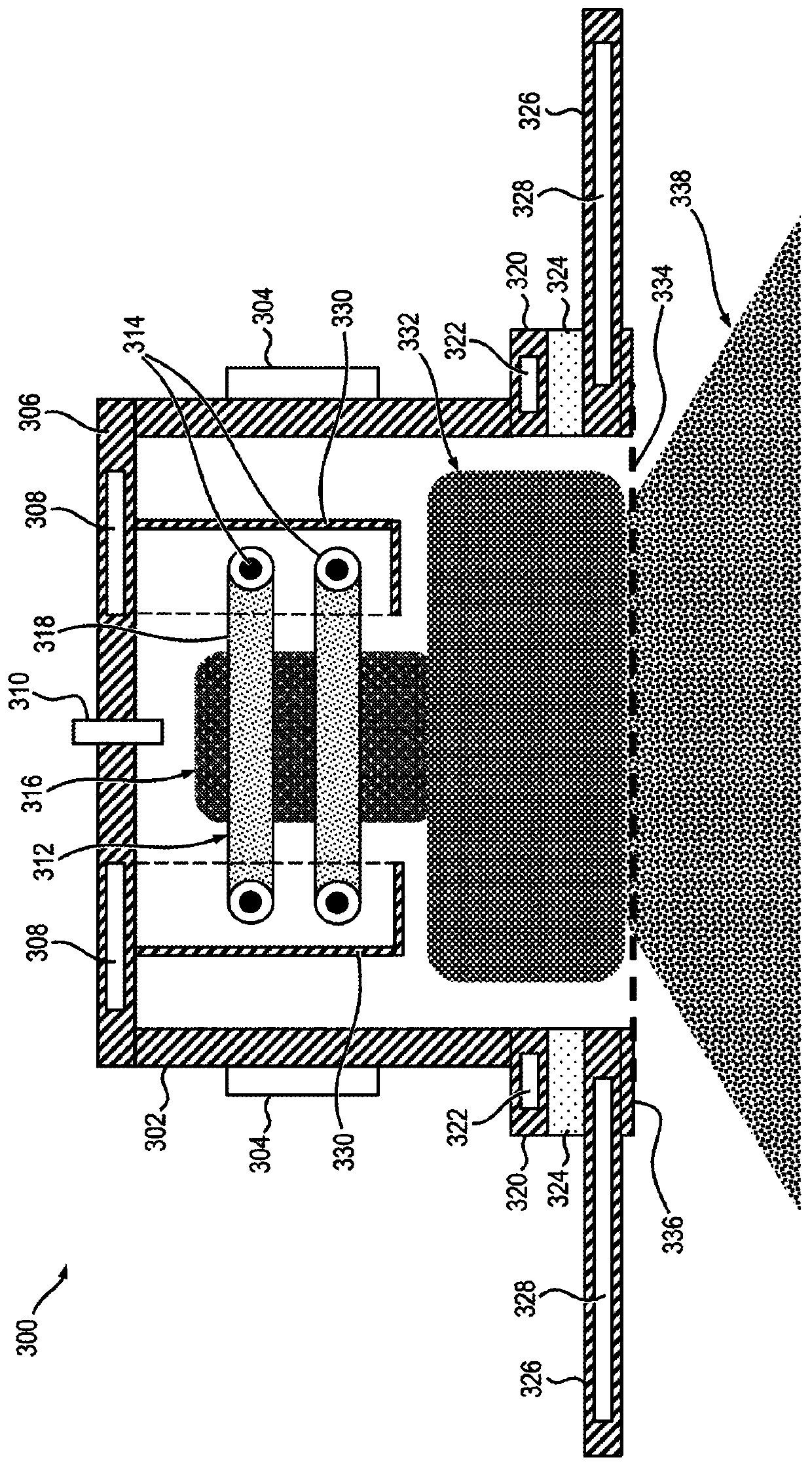
[0091] By way of example only and not limitation, the use of image 3The exemplary plasma ion source 300 shown in FIG. 3 forms a DLC coating on the top surface of a glass substrate. For this example, it is assumed that plasma ion source 300 has an overall length of about 635 mm and a width of about 178 mm; the distance between extraction grid 334 and the top surface of the glass substrate is fixed at about 172 mm. Argon feed gas was supplied to plasma ion source 300 through ceramic porous alumina feed conduit 310 at a rate of about 80 standard cubic centimeters per minute (sccm). Precursor gas was supplied to the vacuum chamber through a precursor gas feed conduit approximately 483 mm in length, which was positioned adjacent to a fixed non-magnetic stainless steel substrate support approximately 431 mm in length and approximately 305 mm in width. The precursor gas feed conduit was positioned approximately 83 mm in front of the top surface of the substrate support and position...
Embodiment 2
[0098] Figure 7 is a graph 700 depicting bias voltage and pulse frequency of the bias voltage versus Figure 6 The effect of ion current density drawn by the exemplary plasma ion source 602 is shown. Depend on Figure 7 The results represented by the illustrated graph 700 are obtained using settings in the outgoing grid component ( Figure 6 Downstream of 638 in , at the base ( Figure 6 640) in front of the Faraday cup detector at a distance of about four inches. The Faraday cup measures from the plasma ion source ( Figure 6 602) in the ion current density (unit: μA / cm 2 ). Such as Figure 7 The graph 700 shows, for the bias supply ( Figure 6 The measured ion current density is plotted against the bias voltage levels (unit: volts) for a number of different pulse frequencies (unit: KHz) (ie 300KHz, 200KHz, 100KHz, 50KHz and 0KHz (ie DC)) in 630 in . In this example, plasma ion source 602 operates with argon as the feed gas, which is passed through gas feed conduit ...
Embodiment 3
[0101] Figure 8 is a description according to an illustrative embodiment of the invention of the bias voltage pair derived from Figure 6 A graph 800 of the effect of ion energy for an exemplary plasma ion source 602 is shown. Depend on Figure 8 The ion energy distribution (dI / dE) results represented by the illustrated graph 800 were obtained by using the settings in the extraction grid assembly ( Figure 6 Downstream of 638), base ( Figure 6 Obtained by measuring ion energy (unit: eV) with a Retarding Field Energy Analyzer (RFEA) (for example, manufactured by Impedans Ltd. of Dublin, Ireland) in front of 640 in . Plasma ion source 602 ( Figure 6 ) operated at an operating pressure of 15 mTorr with an argon feed gas flow rate of 80 sccm and applied to the inductive antenna 610 with 500 watts of RF power ( Figure 6 ).
[0102] When no bias voltage is applied to the plasma chamber 604 ( Figure 6 ), an average ion energy of about 45eV is measured, and the ion energy ...
PUM
| Property | Measurement | Unit |
|---|---|---|
| length | aaaaa | aaaaa |
| width | aaaaa | aaaaa |
| diameter | aaaaa | aaaaa |
Abstract
Description
Claims
Application Information
 - R&D
- Intellectual Property
- Life Sciences
- Materials
- Tech Scout
- Unparalleled Data Quality
- Higher Quality Content
- 60% Fewer Hallucinations
Browse by: Latest US Patents, China's latest patents, Technical Efficacy Thesaurus, Application Domain, Technology Topic, Popular Technical Reports.
© 2025 PatSnap. All rights reserved.Legal|Privacy policy|Modern Slavery Act Transparency Statement|Sitemap|About US| Contact US: help@patsnap.com