Coal pulping system waste gas purification device and coal pulping system waste gas purification process

An exhaust gas purification device and exhaust gas purification technology are applied in the direction of air quality improvement, chemical instruments and methods, and separation methods, which can solve the problems of long process flow and large floor area, so as to improve the absorption efficiency and reduce the generation of waste liquid , Processing efficiency and stable effect

Active Publication Date: 2020-06-09
WANHUA CHEM GRP CO LTD +1
View PDF7 Cites 1 Cited by
  • Summary
  • Abstract
  • Description
  • Claims
  • Application Information

AI Technical Summary

Problems solved by technology

Although this solution can better guarantee the effect of exhaust gas purification treatment, it also has problems such as large footprint and long process flow.

Method used


Image

  • Coal pulping system waste gas purification device and coal pulping system waste gas purification process
  • Coal pulping system waste gas purification device and coal pulping system waste gas purification process
  • Coal pulping system waste gas purification device and coal pulping system waste gas purification process

Examples


Embodiment 1

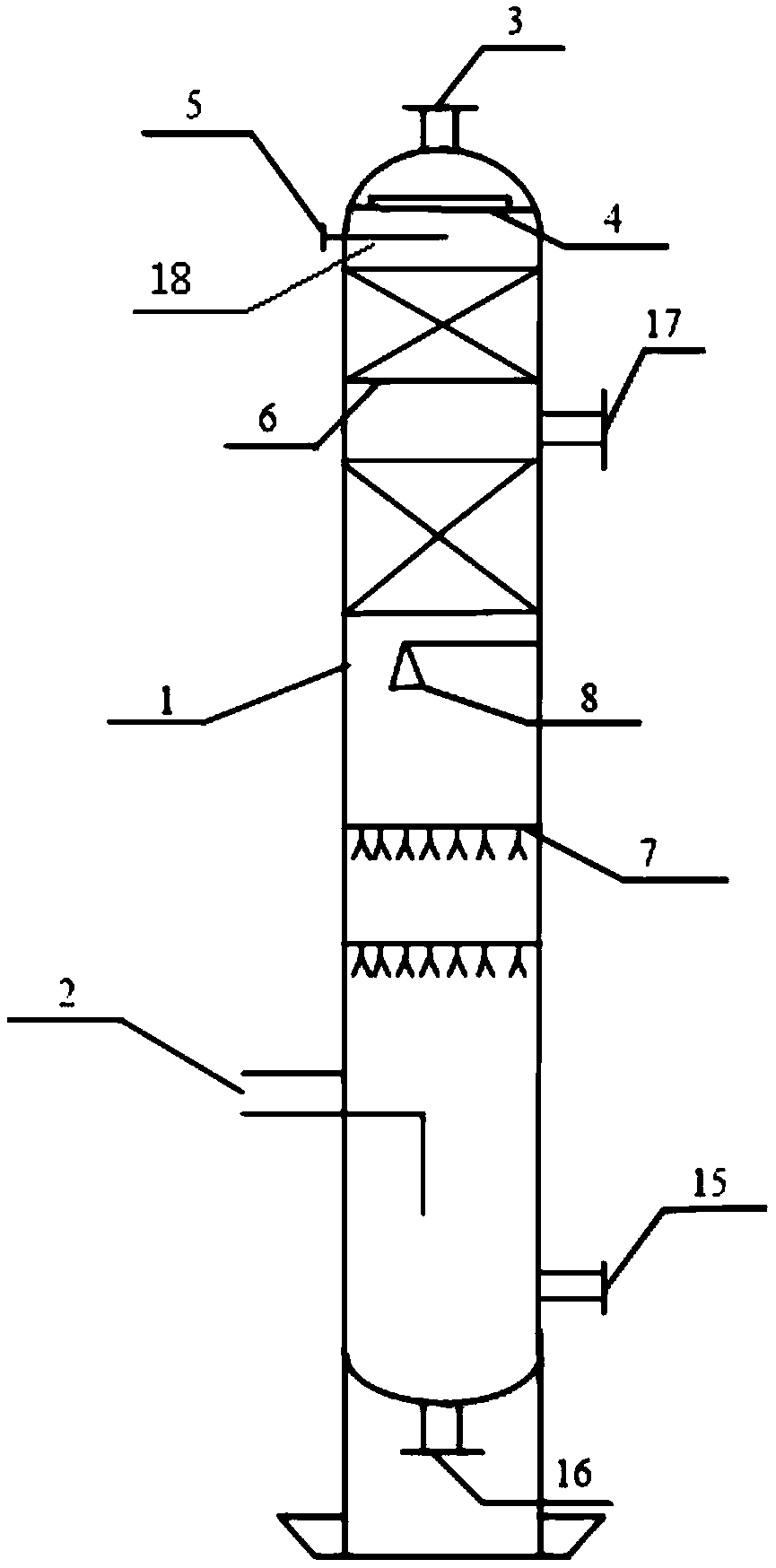
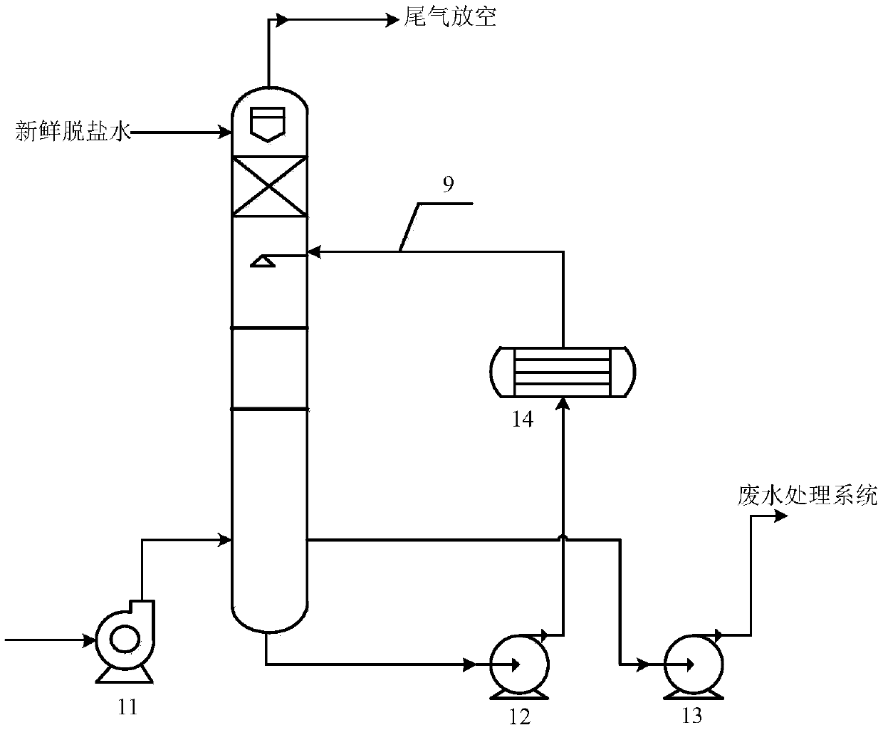
[0057] Such as figure 1 As shown, the exhaust gas purification tower 1 of this embodiment includes a tower body, an air inlet 2 is arranged at the bottom of the tower body, an air outlet 3 and a wire mesh demister 4 are arranged at the top, a fresh absorption liquid inlet 5, and a trough distributor 18 . Two packing support screens 6 are arranged inside the tower body, and fillers are placed on the packing support screens 6 to form a packing layer, and nozzles (circulating liquid spray nozzles) are arranged between the fresh absorption liquid absorption section and the circulating liquid absorption section. device) 8; a plurality of gas-liquid flow uniform distribution devices 7 are set between the circulating liquid spray nozzle device (nozzle 8) and the exhaust gas inlet (air inlet 2) in the circulation absorption section; the nozzle 8 passes through the acid and alkali resistant pipeline 9 and the circulating water pump 12 are connected to each other (the packing is not dra...

Embodiment 2

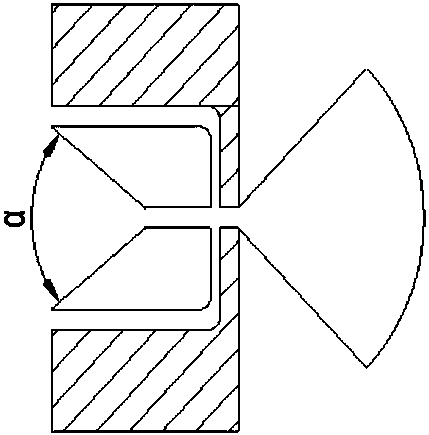
[0065] Such as figure 1 As shown, the exhaust gas purification tower 1 of this embodiment includes a tower body, an air inlet 2 is arranged at the bottom of the tower body, an air outlet 3 and a wire mesh demister 4 are arranged at the top, a fresh absorption liquid inlet 5, and a trough distributor 18 . There are two packing support screens 6 inside the tower body, and fillers are placed on the packing support screens 6 to form a packing layer; high-efficiency conical nozzles (circulating fluid nozzles) 8 are arranged between the packing layers, and the conical nozzles 8 pass through the resistant The acid-base pipeline 9 and the circulating water pump 12 are connected to the liquid in the bottom of the tower (the packing is not shown in the figure).

[0066] The exhaust gas purification tower is equipped with a centrifugal pumping machine 11, which can be adjusted by frequency conversion to realize energy saving while ensuring the pumping effect. A circulating water pump 12...


PUM


Abstract

The invention provides a coal pulping system waste gas purification device and a coal pulping system waste gas purification process, wherein the waste gas purification tower of the treatment system has excellent purification treatment capacity while the treated coal pulping system waste gas can meet the tail gas emission standard, and the yield of wastewater can be remarkably reduced. The processdisclosed by the invention comprises the following steps: collecting waste gas by virtue of a centrifugal negative-pressure pumping machine, enabling the waste gas to enter a purification tower, enabling the waste gas to be in full contact with a circulating liquid sprayed by an efficient conical nozzle on a gas-liquid flow distributor, and performing secondary absorption treatment on fresh liquidof a groove-type water distributor, wherein the absorbed waste gas is directly discharged to the outside to reach the emission standard, part of the tower kettle circulating liquid is discharged to awastewater treatment process, and part of the tower kettle circulating liquid exchanges heat and returns to the purification tower again. The invention also provides an absorption liquid used in themethod, wherein the absorption liquid has the characteristics of high efficiency, multiple functions, low cost and the like.

Description

technical field [0001] The invention belongs to the technical field of chemical waste gas treatment, and relates to a waste gas purification device and process of a coal pulping system. Background technique [0002] Coal water slurry (CWM) is a clean coal-based fluid fuel prepared by a coal slurry process with about 63wt% of raw coal with different particle size distributions, 36wt% of water and about 1wt% of additives. Coal-water slurry gasification technology turns solid coal fuel into fluid coal fuel, making it have the application characteristics of liquid combustion similar to heavy oil, which greatly promotes the clean utilization of coal, not only can achieve better environmental benefits, It can also obtain considerable economic benefits of replacing oil and energy saving benefits. [0003] However, in the coal gasification industry, the wastewater in the industrial chain is generally difficult to treat. Therefore, the coal pulping system also assumes the responsibi...

Claims


Application Information

Patent Timeline
Patent Type & Authority Applications(China)
IPC IPC(8): B01D53/78B01D53/72B01D53/58B01D53/54
CPCB01D53/78B01D53/58B01D53/72B01D53/54B01D2251/60Y02P70/10
Inventor 楼家伟孙路滨胡耀峰王阳郝成浩张宏科孙得浩何晓方姜良建
Owner WANHUA CHEM GRP CO LTD
Why Eureka
Try Eureka