Gas pipeline weld joint protection device

A protection device and gas pipeline technology, applied in auxiliary devices, welding equipment, auxiliary welding equipment, etc., can solve the problems of not allowing repairs, waste of manpower and material resources, saving manpower and material resources, increasing compressive strength, and uniform force Effect

Active Publication Date: 2020-06-09
山东泰阳特种设备检测科技有限公司
8 Cites 0 Cited by

AI-Extracted Technical Summary

Problems solved by technology

Therefore, in the construction of long-distance pipelines, crack defects are not allowed to exist, and usually they are not a...

Method used

[0025] Roller 19 two ends are respectively coaxially fixed spacer 4, and spacer 4 can prevent ring 1 from shifting in the course of work, avoiding the danger of its falling.
[0028] Crowbar 14 inboard evenly distributed retaining rod 15, hinged locking lever 16 on the chassis 11 upper surface, locking...

Abstract

The invention relates to a gas pipeline weld joint protection device, and belongs to the field of oil and gas transmission. The device comprises a chassis, wherein two front wheels are installed on the two sides of the front end of the chassis correspondingly, two rear wheels are installed at the rear end of the chassis, two main hydraulic cylinders are vertically fixed to the upper surface of thechassis, piston rods of the two main hydraulic cylinders are fixed to the same lifting disc, two auxiliary hydraulic cylinders are vertically fixed to the two sides of the lifting disc correspondingly, piston rods of the two auxiliary hydraulic cylinders are fixed to the same transverse rod, vertical rods are vertically fixed to the two ends of the transverse rod correspondingly, rotating rollersare installed on the two vertical rods correspondingly, the distance between the two rotating rollers is smaller than the diameter of a pipeline, two Y-shaped frames are vertically fixed to the two sides of the lifting disc correspondingly, and a rotating shaft is supported by the Y-shaped frames. According to the device, the welding position of the pipeline is protected through a ring, the situation that due to huge pressure of the pipeline, defective weld joints crack, and accidents happen is avoided, meanwhile, manpower and material resources are saved, and oxidation corrosion of the welding position can be avoided.

Application Domain

Welding/cutting auxillary devicesAuxillary welding devices +1

Technology Topic

Gas pipelinePipe welding +8

Image

  • Gas pipeline weld joint protection device
  • Gas pipeline weld joint protection device
  • Gas pipeline weld joint protection device

Examples

  • Experimental program(1)

Example Embodiment

[0019] Embodiments of the present invention are further described below in conjunction with accompanying drawings:
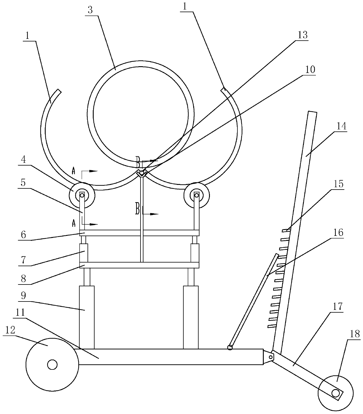
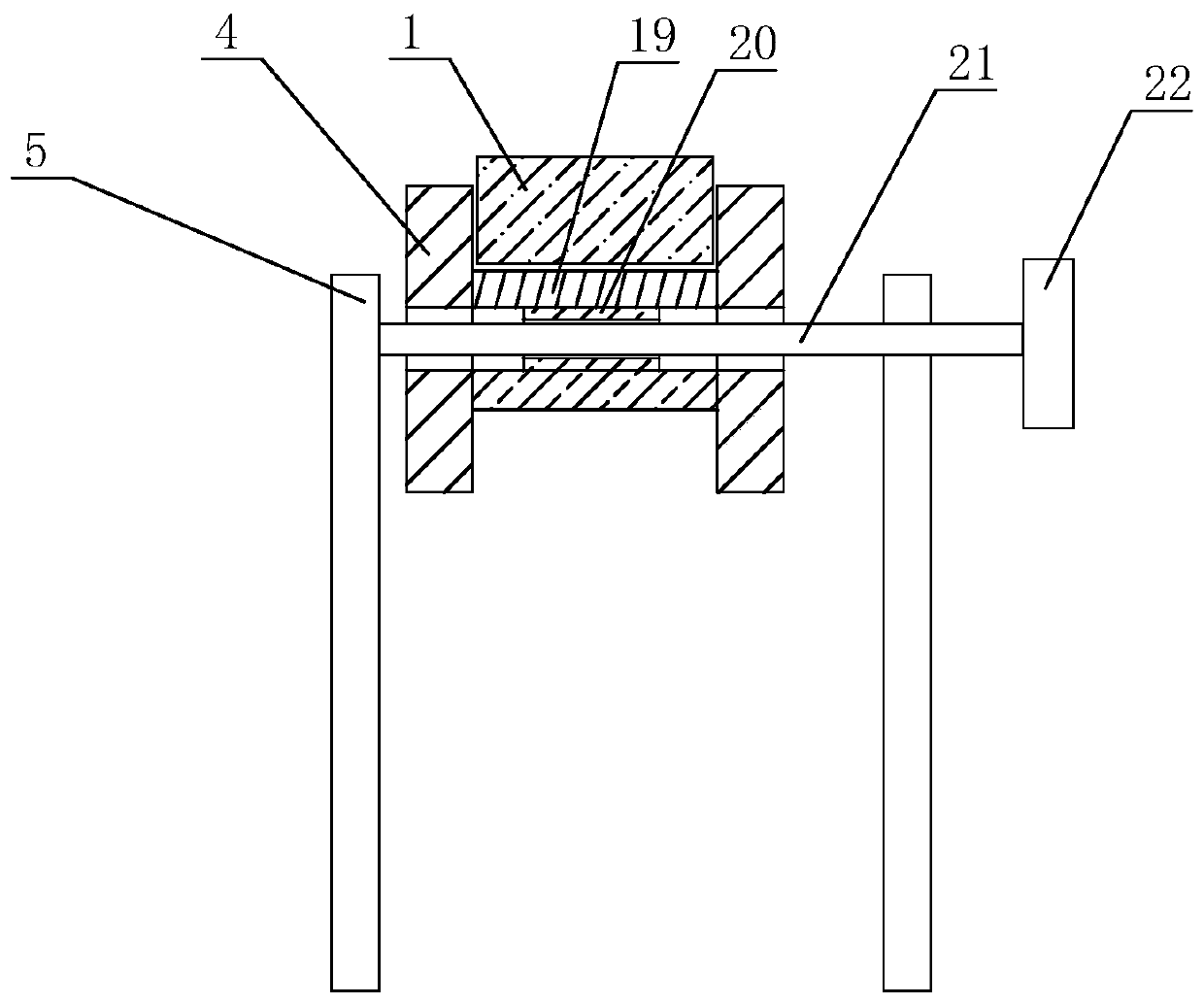
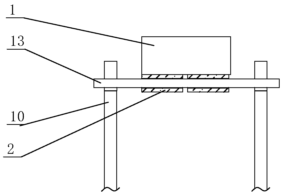
[0020] like Figure 1-Figure 3 as shown,
[0021] The gas pipeline weld protection device of the present invention comprises a chassis 11, two front wheels 12 are respectively installed on both sides of the front end of the chassis 11, two rear wheels 18 are respectively installed on the rear end of the chassis 11, and two main wheels 18 are vertically fixed on the upper surface of the chassis 11. Hydraulic cylinder 9, the piston rods of the two main hydraulic cylinders 9 are fixed on the same lifting plate 8, and the two auxiliary hydraulic cylinders 7 are vertically fixed on both sides of the lifting plate 8, and the piston rods of the two auxiliary hydraulic cylinders 7 are fixed On the same cross bar 6, the two ends of the cross bar 6 vertically fix the vertical rods 5 respectively, and the turning rollers 19 are respectively installed on the two vertical bars 5. Two Y-shaped frames 10 are vertically fixed respectively, and a rotating shaft 13 is mounted on the Y-shaped frames 10;
[0022] It includes two semi-circular rings 1, the lower ends of the two rings 1 are fixed with sleeves 2 of the same specification, the two sleeves 2 are set on the rotating shaft 13, the two rings 1 are placed on the two rotating rollers 19 respectively, and the inner diameter of the ring 1 is Corresponds to the outer diameter of the pipe 3.
[0023] Working principle and process:
[0024] When working, push the chassis 11 to the bottom of the pipe 3, then start the main hydraulic cylinder 9, the main hydraulic cylinder 9 drives the lifting plate 8 to rise, and at the same time drives the ring 1 to rise, when the lower end of the ring 1 touches the wall of the pipe 3, stop the main hydraulic cylinder 9. Then the auxiliary hydraulic cylinder 7 is started, and the auxiliary hydraulic cylinder 7 drives the two rotating rollers 19 to rise, and the two rings 1 rotate around the rotating shaft 13, thereby forcing the two rings 1 to close together. During this process, the rotating rollers 19 are on the outer wall of the ring 1 scroll. The distance between the two turning rollers 19 is smaller than the diameter of the pipeline 3, so the turning rollers 19 will not break away from the ring 1 during the closing process. When the upper ends of the two rings 1 contact, stop the auxiliary hydraulic cylinder 7, then weld and fix between the ring 1 and the ring 1, between the ring 1 and the wall of the pipeline 3, the weld seam is protected, and the resistance of the weld is increased. High compressive strength, saving manpower and material resources for repair, and avoiding oxidation and corrosion of welds.
[0025] The two ends of the rotating roller 19 are respectively coaxially fixed with a limit plate 4, and the limit plate 4 can prevent the ring 1 from shifting during the working process and avoid the danger of its falling.
[0026] Coaxial fixed nut 20 in the rotating roller 19, cooperates screw rod 21 in the nut 20, screw rod 21 two ends are installed on the vertical rod 5 by bearing respectively, and screw rod 21 ends are fixedly twisted handle 22. There must be misalignment after the ring 1 is closed, and the steel ring 1 is heavy and cannot be moved purely by manpower. Therefore, the limit plate 4 is driven by screwing the screw 21 to feed, and then the ring is pushed by the feeding method 1. Align the ends of the two rings 1 to avoid the reduction of the fixing strength due to misalignment, which is safe and labor-saving.
[0027] Two rear wheels 18 are installed on the shaft, and the shaft is installed on the jacking rod 17, and the jacking rod 17 is hinged on the tail end of the chassis 11, and the jacking rod 17 is fixed at a certain angle to the crowbar 14. Under normal conditions, the jacking rod 17 Located on the outside of the chassis 11. The working ground of the field operation is usually uneven, mostly sandy soil or stone ground, so the jacking rod 17 is rotated by turning the crowbar 14, and then the tail end of the chassis 11 is jacked up or lowered to adapt to the uneven ground and ensure the environment. The ring 1 is parallel to the axis of the pipe 3 .
[0028] Crowbar 14 inner side evenly distributes stop bar 15, and hinged lock bar 16 is hinged on the upper surface of chassis 11, and lock bar 16 rides on the stop bar 15. When the chassis 11 is tilted, the locking bar 16 rotates due to its own gravity and rides between the corresponding adjacent blocking bars 15, thereby restricting the rotation of the crowbar 14 to the front end. The structure is simple, safe and labor-saving.

PUM

no PUM

Description & Claims & Application Information

We can also present the details of the Description, Claims and Application information to help users get a comprehensive understanding of the technical details of the patent, such as background art, summary of invention, brief description of drawings, description of embodiments, and other original content. On the other hand, users can also determine the specific scope of protection of the technology through the list of claims; as well as understand the changes in the life cycle of the technology with the presentation of the patent timeline. Login to view more.

Similar technology patents

Preparation method for double-layer PET protective film for lithium battery pack

ActiveCN105778804AAvoid filiform cracksHigh compressive strength
Owner:SUZHOU SIDIKE NEW MATERIALS SCI & TECH

Porous polymer filling material for biotrickling filter

InactiveCN106630114AImproved melt strengthHigh compressive strength
Owner:HEFEI INNOVATION LIGHTWEIGHT MATERIALS

Classification and recommendation of technical efficacy words

  • High compressive strength
  • Save manpower and material resources

Stone aggregate wrapped by microfine fibre polymer mortar thin layer and preparation method thereof

InactiveCN101863631AHigh compressive strengthStrong resistance to deformation
Owner:NANTONG ZHONGRUN CONCRETE +1

Roller mill for comminuting brittle grinding stock

ActiveUS20120111982A1high compressive strengthhigh impact
Owner:THYSSENKRUPP POLYSIUS AKTIENGES

Inorganic foam heat insulating material with second-grade closed-pore structure and preparation method thereof

InactiveCN102807387AImprove thermal insulation performanceHigh compressive strength
Owner:HEBEI YL BANGDA NEW MATERIALS LTD CO +1

Polycrystal flexible tile joint mixture

InactiveCN103172332AImprove the lack of penetration and gripHigh compressive strength
Owner:HAIDA CONSTR GRP

Automatic feeding assembling and transmitting device for electronic elements

InactiveCN102612311AAutomate operationSave manpower and material resources
Owner:深圳市中科创安科技有限公司
Why Eureka
Try Eureka