Carrier roller shaft production line device

A technology of production line equipment and idler shafts, which is applied to other manufacturing equipment/tools, manufacturing tools, etc., can solve the problems of insufficient cutting precision of workpieces, unsatisfactory working effects and efficiency of mechanisms, and inability to achieve accurate and stable feeding units.

Active Publication Date: 2020-06-09
FUZHOU SANXUN MACHINERY
View PDF8 Cites 1 Cited by
  • Summary
  • Abstract
  • Description
  • Claims
  • Application Information

AI Technical Summary

Problems solved by technology

The automatic feeding mechanism 100 has the following disadvantages: 1), the unloading table 111 is full of idler shafts, and when the ejector plate 112 moves upward under the action of the ejector cylinders 113 on both sides, its upper end face tends to be supported. It is impossible to ensure that only one idler shaft is lifted at a time by lifting multiple idler shafts to the workpiece placement table 121. Therefore, the feeding unit in this way cannot be accurate and stable, resulting in unstable and unstable work of the entire mechanism. precise
2) When the ejector plate 112 descends, the idler roller shafts piled up on the discharge table 111 will roll forward due to gravity, and the ejector plate 112 will be subjected to a strong impact, which will affect the stability and safety of the entire mechanism, and increased noise
3) The workpiece placement table 121 is a whole plate, and the iron filings during the processing are easy to fly in and stay on it, affecting the rolling discharge of the idler shaft, and the detection of the sensor 123 and the subsequent adjustment of the workpiece will be affected. Cause the work effect and efficiency of the whole organization to be unsatisfactory
4), the inductor 123 is arranged in the middle of the two stop blocks 122, therefore, only the middle part can be detected, and it cannot be guaranteed that the two ends of the idler shaft that rolls down to the work placement table 121 lean against the two stop blocks 122, cause inaccurate detection
This tool assembly processing unit 230 has the following disadvantages: 1), the reciprocating motion of the first rack 2302 on the X axis is converted into the reciprocating motion of the toothed slide 2304 on the Y axis, thereby driving the toothed slide 2304 fixedly connected The reciprocating motion of the tool holder 2305, the transmission mechanism of this mode is found in practice, the first rack 2302 rack drives the first gear 2303, and the first gear 2303 drives the toothed slide seat 2304, due to the gap between the gear and the rack The gap between them is large, and the error that occurs during transmission is accumulated twice, resulting in insufficient cutting accuracy of the workpiece
In practice, it is found that the weight of this single-tool seat structure is eccentric when rotating, and the swing is relatively severe, which greatly affects the working performance.
3) The drill bit 2307 is set on the tool seat, and the machining process of punching the center hole of the idler shaft is performed through the movement of the tool seat. Since the drill bit needs to move to the central axis of the idler shaft when drilling the center hole, the tool seat moves Due to the precision error in the process, the drill bit cannot be accurately moved to the central axis of the idler shaft, and the machined center hole has a large precision error and low concentricity
[0007] 3. The machine tool only completes the four processes of turning the end face, chamfering, punching the center hole, and cutting the spring groove, and the fifth process of milling and flattening needs to be processed on other equipment
Low efficiency, poor quality, not suitable for high-volume processing
For example: Chinese invention patent ZL201410570827.6 discloses a roller shaft milling and flattening machine. The disadvantages of this milling and flattening machine are: single-head milling and flattening, which requires a U-turn, and the efficiency is not high. After the U-turn, the flattened surface is inconsistent; The milling height cannot be adjusted, so it cannot be applied to the processing of various specifications and thicknesses; the belt transmission efficiency is low, and the belt is easy to slip or break; the milling position of the workpiece is manually positioned, and the positioning accuracy is not high; the geared motor is installed in the air , easy to vibrate during milling, prone to accidents

Method used


Image

  • Carrier roller shaft production line device
  • Carrier roller shaft production line device
  • Carrier roller shaft production line device

Examples


Embodiment Construction

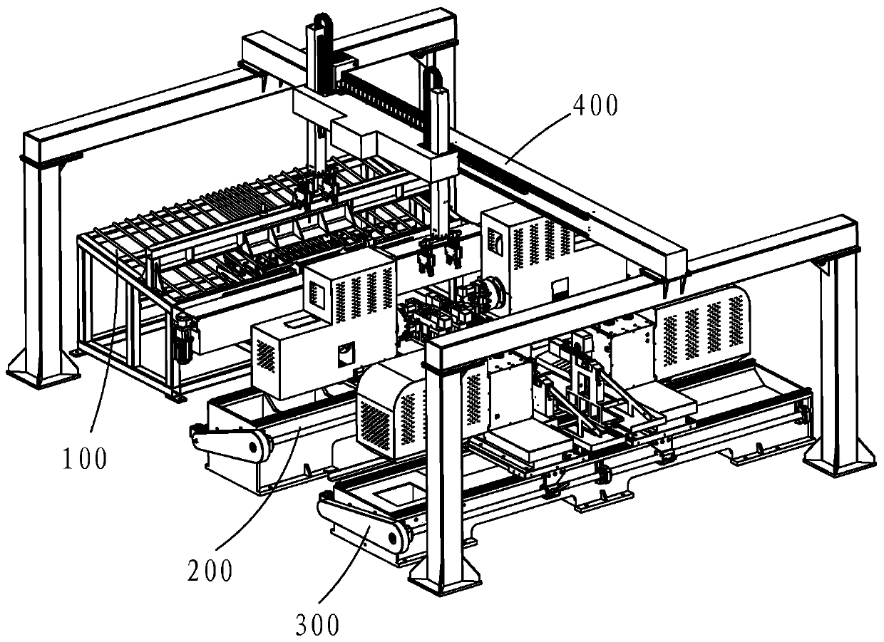
[0087] Such as figure 1 As shown, an idler shaft production line equipment includes an automatic feeding mechanism 100, a machine tool 200 integrated with end face chamfering and center holes of all circlip tankers, a double-head CNC milling and flattening machine 300, an automatic grabbing mechanism 400 and a Control mechanism 500 .

[0088] The control mechanism 500 is respectively connected with the automatic feeding mechanism 100, the machine tool 200 integrated with the end face chamfering of the spring groove car and the center hole punching, the double-head CNC milling and flattening machine 300 and the automatic grabbing mechanism 400.

[0089] The control mechanism 500 controls the automatic feeding mechanism 100 to feed the machine tool 200 integrated with the end face chamfering of the circlip groove car and punches the center hole. The control mechanism 500 controls the automatic material grabbing mechanism 400 to grab downwards and move the workpieces that reach t...


PUM


Abstract

The invention relates to a carrier roller shaft production line device. The carrier roller shaft production line device comprises an automatic feeding mechanism, a machine tool integrated with clamp spring grooving, end face turning, chamfering and centering, a double-head numerical control flat milling machine, an automatic grabbing mechanism and a control mechanism; the control mechanism is respectively connected with the automatic feeding mechanism, the machine tool integrated with clamp spring grooving, end face turning, chamfering and centering, the double-head numerical control flat milling machine and the automatic grabbing mechanism; the control mechanism controls the automatic feeding mechanism to feed the machine tool, and controls the automatic grabbing mechanism to grab a workpiece reaching an outlet of the automatic feeding mechanism downwards and move the workpiece onto the machine tool, and then the workpiece is subject to machining operations including clamp spring grooving, end face turning, chamfering and centering; and after being machined, the workpiece is moved to the double-head numerical control flat milling machine by controlling the automatic grabbing mechanism to be subject to a flat milling process, and then the workpiece is discharged. According to the carrier roller shaft production line device, five processes of end face turning, chamfering, centering, clamp spring grooving and flat milling are achieved on the same production line, and the production efficiency is improved.

Description

【Technical field】 [0001] The invention belongs to the technical field of mechanical equipment, and in particular relates to a production line equipment of idler shafts. 【Background technique】 [0002] The idler shaft is an important accessory of the belt conveyor. On the one hand, its main function is to hold up the conveyor belt and the materials on the conveyor belt, and on the other hand, it uses the friction between it and the conveyor belt to drive the idler tube, Bearing seat, bearing outer ring and seals rotate to realize material transmission together with conveyor belt. [0003] The specific process of processing the idler shaft includes five processing processes: end face turning, chamfering, center hole drilling, spring groove cutting, and milling and flattening. [0004] Chinese invention patent ZL201810076900.2 discloses a machine tool for cutting the circlip groove, turning the end face, chamfering and punching the center hole of the idler shaft. These four f...

Claims


Application Information

Patent Timeline
Patent Type & Authority Applications(China)
IPC IPC(8): B23P23/06
CPCB23P23/06
Inventor 林东林典林强
Owner FUZHOU SANXUN MACHINERY
Why Eureka
Try Eureka