Hybrid power driving system and vehicle

A drive system and hybrid technology, applied in hybrid vehicles, fluid pressure actuation system components, motor vehicles, etc., can solve the problems of poor smoothness and frustration of shifting

Active Publication Date: 2020-06-09
BYD CO LTD
View PDF7 Cites 7 Cited by
  • Summary
  • Abstract
  • Description
  • Claims
  • Application Information

AI Technical Summary

Problems solved by technology

[0006] The technical problem to be solved by the present invention is to provide a hybrid drive for the prior art that adopts a synchronizer and two clutches to shift gears together, so that there will be a certain setback in the shifting process and the smoothness of shifting is poor. Systems and Vehicles

Method used


Image

  • Hybrid power driving system and vehicle
  • Hybrid power driving system and vehicle
  • Hybrid power driving system and vehicle

Examples


no. 1 example

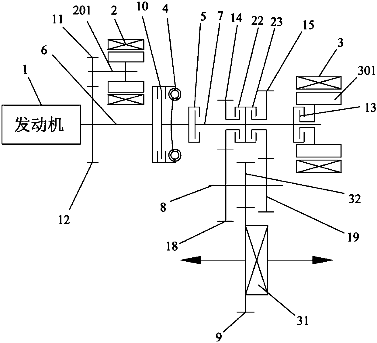
[0071] like figure 1 As shown, the hybrid drive system provided by the first embodiment of the present invention includes an engine 1, a first motor 2, a second motor 3, a torque converter 4, a first clutch 5, a second clutch 13, and an engine output shaft. 6 and a transmission, the transmission includes a transmission input shaft 7, a transmission output shaft 8, a transmission gear mechanism and a shift synchronization mechanism.

[0072] The transmission output shaft 8 is fixedly connected with an output gear 32 that meshes with the differential gear 9 . The differential gear 9 is provided on the housing of the differential 31 . The differential gear 9 rotates together with the housing of the differential 31 . In this way, the transmission output shaft 8 outputs power to the differential 31 .

[0073] The torque converter 4 is provided with a lock-up clutch 10 , and the shift synchronization mechanism includes a first gear clutch 22 and a second gear clutch 23 .

[0074...

no. 2 example

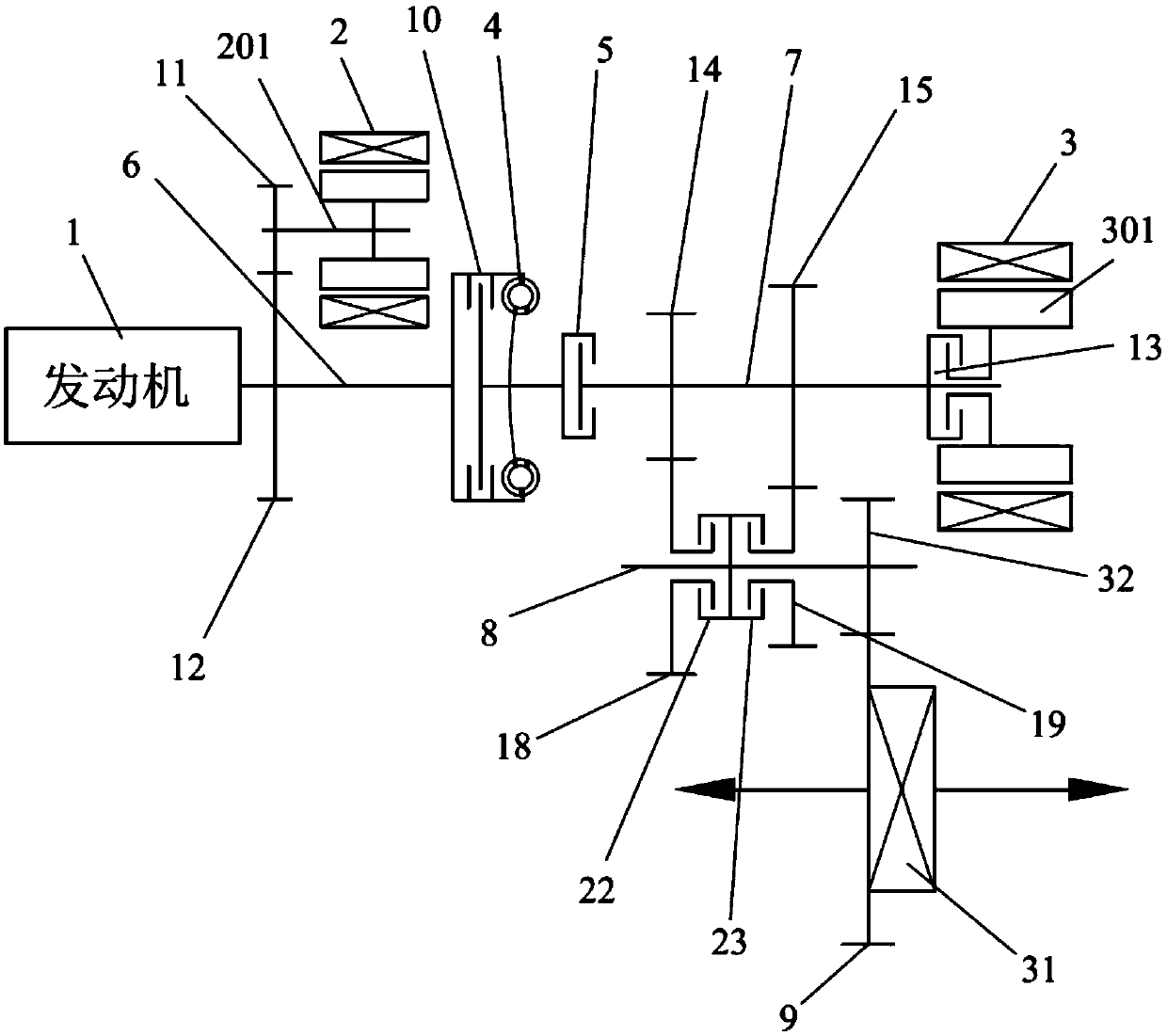
[0109] figure 2 Shown is the hybrid power system provided by the second embodiment of the present invention, which is different from the first embodiment in that the first gear driving gear 14 and the second gear driving gear 15 are fixed on the transmission input shaft 7 Above, the first gear driven gear 18 and the second gear driven gear 19 are idly sleeved on the transmission output shaft 8, and the first gear clutch 22 and the second gear clutch 23 are arranged on the on the transmission output shaft 8.

[0110] The first gear clutch 22 is selectively engaged or disengaged to control the engagement or disengagement of the first gear driven gear 18 with the transmission output shaft 8 , and the second gear clutch 23 is selectively engaged or disengaged. ground to engage or disengage to control the engagement or disengagement of the second gear driven gear 19 with the transmission output shaft 8 .

[0111] The first clutch 5, the first gear driving gear 14, the second gea...

no. 3 example

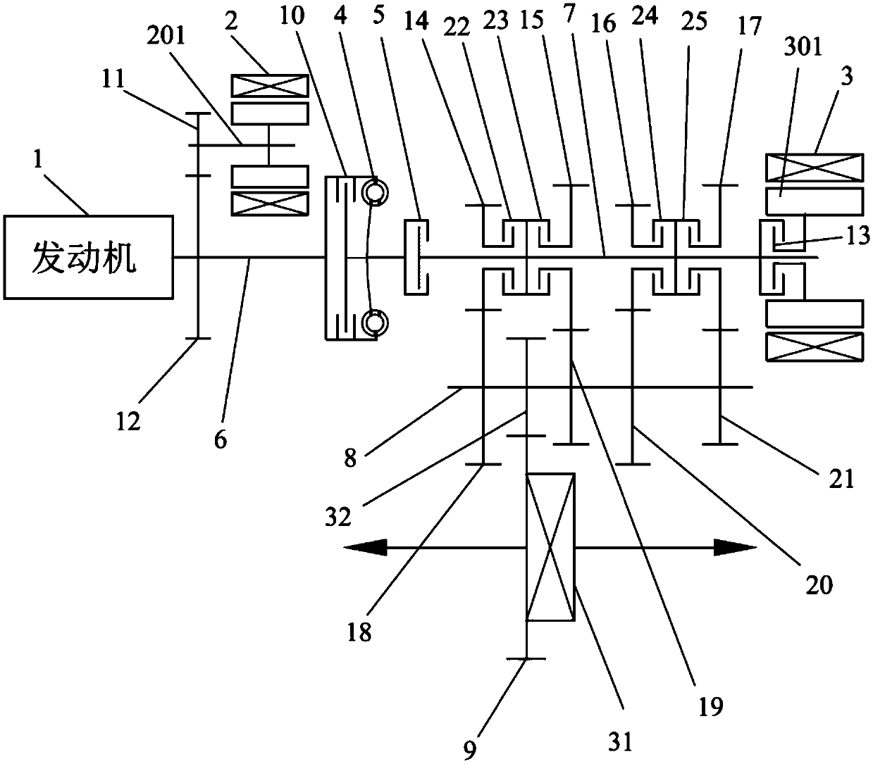
[0113] image 3 Shown is the hybrid power system provided by the third embodiment of the present invention, which is different from the first embodiment in that the number of gears is different. In the third embodiment, there are 4 sets of gears.

[0114] like image 3As shown, specifically, the plurality of gear driving gears include a first gear driving gear 14, a second gear driving gear 15, a third gear driving gear 16 and a fourth gear driving gear 17, and the plurality of gears are The gear driving gear includes a first gear driven gear 18, a second gear driven gear 19, a third gear driven gear 20 and a fourth gear driven gear 21. The first gear driving gear 14. The second gear driving gear 15, the third gear driving gear 16 and the fourth gear driving gear 17 are idle on the transmission input shaft 7, the first gear driven gear 18, the second gear The driven gear 19, the driven gear 20 of the third gear and the driven gear 21 of the fourth gear are fixed on the outpu...


PUM


Abstract

The invention belongs to the technical field of hybrid power, and relates to a hybrid power driving system and a vehicle. The hybrid power driving system comprises an engine, an engine output shaft, afirst motor, a second motor, a hydraulic torque converter, a first clutch and a transmission, the transmission comprises a transmission input shaft, a transmission output shaft, a speed change gear mechanism and a gear shifting synchronizing mechanism, the hydraulic torque converter is provided with a locking clutch, and the gear shifting synchronizing mechanism only comprises one or more clutches. According to the hybrid power driving system and the vehicle, gear shifting is achieved through combination of the hydraulic torque converter and the clutch(es), a gear shifting synchronizer adopted by an existing transmission is omitted, and the gear shifting smoothness is good. The vehicle adopting the hydraulic torque converter has the advantages of being stable and comfortable in starting,easy to operate by a driver and the like, and is more suitable for urban working conditions or non-road working conditions.

Description

technical field [0001] The invention belongs to the technical field of hybrid power, and in particular relates to a hybrid power driving system and a vehicle. Background technique [0002] Hybrid systems can improve vehicle fuel economy in several ways. For example, the engine can be switched off during idling, deceleration or braking, driving in pure electric drive mode to eliminate efficiency losses due to engine drag. In addition, the energy stored in the power battery generated by regenerative braking or generated by the electric motor during engine operation can be utilized in pure electric drive mode, or supplement the engine's torque or power in hybrid drive mode. [0003] A hybrid vehicle can be driven by combining at least two different power sources. At present, most hybrid vehicles use a gasoline-electric hybrid system, which includes an engine powered by fuel and an electric motor driven by electricity. In order to improve the combustion efficiency of the engin...

Claims


Application Information

Patent Timeline
Patent Type & Authority Applications(China)
IPC IPC(8): B60K6/24B60K6/26B60K6/36B60K6/547F16H57/023F16H63/30F16H61/30F15B21/042F16D23/02
CPCB60K6/24B60K6/26B60K6/36B60K6/547F15B21/042F16D23/02F16H57/023F16H61/30F16H63/30F16H2306/00Y02T10/62
Inventor 廉玉波凌和平翟震梅绍坤熊雨超
Owner BYD CO LTD
Why Eureka
Try Eureka