
Control method for drying and granulating, and vertical drying-and-granulating integrated equipment adopting same

A control method and granulation technology, applied in chemical instruments and methods, granulation in static tanks/tanks, dehydration/drying/thickened sludge treatment, etc., can solve problems such as numerous control factors, serious loss, and high cost , to achieve the effect of simple control method and accurate water content

Active Publication Date: 2020-06-09
青绿智慧(福建省)环保能源科技有限公司
View PDF7 Cites 0 Cited by
  • Summary
  • Abstract
  • Description
  • Claims
  • Application Information

AI Technical Summary

Problems solved by technology

However, this method is a method of statically judging the moisture content, and the error is relatively large. The moisture content of the treated sludge obtained is often far from the target moisture content. Not only is the calculation process complicated, there are many control factors, and the drying effect is not satisfactory.
[0004] 2. The moisture content of the sludge in the tank can be judged in real time by installing an instrument to detect the moisture content in the drying tank. The working principle of the drying tank is to realize the drying of the sludge by heating and stirring, which makes the equipment set in the tank The moisture content detection instrument is easily damaged, and the instrument that can detect the moisture content of the sludge online in real time is expensive, which makes the method expensive and the loss is serious

Method used


Image

  • Control method for drying and granulating, and vertical drying-and-granulating integrated equipment adopting same
  • Control method for drying and granulating, and vertical drying-and-granulating integrated equipment adopting same
  • Control method for drying and granulating, and vertical drying-and-granulating integrated equipment adopting same

Examples


Embodiment Construction

[0042] The present invention will be further described below in conjunction with the accompanying drawings and embodiments.

[0043] It should be pointed out that the following detailed description is exemplary and is intended to provide further explanation to the present application. Unless defined otherwise, all technical and scientific terms used herein have the same meaning as commonly understood by one of ordinary skill in the art to which this application belongs.

[0044] It should be noted that the terminology used here is only for describing specific implementations, and is not intended to limit the exemplary implementations according to the present application. As used herein, unless the context clearly dictates otherwise, the singular is intended to include the plural, and it should also be understood that when the terms "comprising" and / or "comprising" are used in this specification, they mean There are features, steps, operations, means, components and / or combina...


PUM

PropertyMeasurementUnit
thicknessaaaaaaaaaa
widthaaaaaaaaaa

Abstract

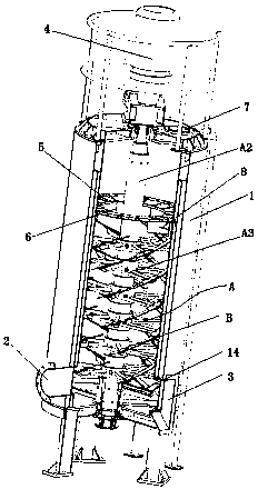
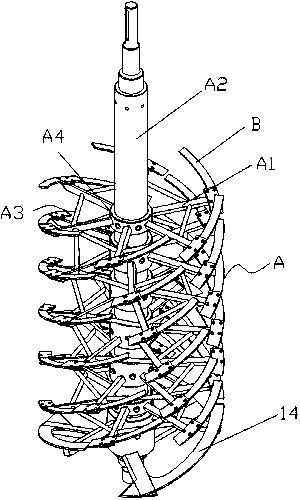
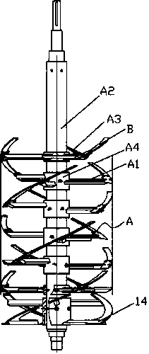
The invention relates to a control method for drying and granulating, and vertical drying-and-granulating integrated equipment adopting the same. The method comprises the following steps: controllinga cutter shaft assembly to rotate by adopting a motor so as to stir or cut a material to be dried, and judging whether the moisture content of the material to be dried meets a requirement or not through the output current of the motor. The equipment comprises a vertical tank body and the cutter shaft assembly arranged in the vertical tank body, wherein interrupted spiral strip-shaped blades are distributed on the cutter shaft assembly, a cutting edge is arranged on the front end edge of each blade, and each blade is connected to the cutter shaft assembly through a connecting rod. The equipmentfurther comprises a central control module, the motor connected with the central control module and used for driving the cutter shaft assembly to rotate so as to stir, convey or cut materials to be dried in the tank body, and a current sensor used for collecting the current of the motor. Whether the moisture content of the to-be-dried material in the tank body meets the requirement or not can bejudged only by detecting the current of the motor, and the control method is simple in process, low in cost and high in practicability and economical efficiency.

Description

technical field [0001] The invention relates to the technical field of sludge treatment, in particular to a drying and granulation control method and vertical drying and granulation integrated equipment using the method. Background technique [0002] With the increase of urban population, the amount of urban sewage and sludge that needs to be treated is increasing, and there are also various sludge drying and sludge drying equipment. In the prior art, when the sludge is dried, its water content is an important indicator to judge whether the drying is completed. The material in the tank is dried), and the moisture content detection instrument cannot be directly installed in the tank, resulting in the inability to estimate the moisture content of the sludge in the tank. Existing approaches include the following two: [0003] 1. According to the set target moisture content, the drying time corresponding to the moisture content is calculated through comprehensive factors such ...

Claims


Application Information

Patent Timeline
Patent Type & Authority Applications(China)
IPC IPC(8): C02F11/13C02F11/00B01J2/10
CPCC02F11/13C02F11/00B01J2/10Y02W10/37
Inventor 刘建津
Owner 青绿智慧(福建省)环保能源科技有限公司
Learn More