Unpowered automatic baffling type biogas generating device

A biogas generating device and baffle-type technology, applied in biochemical cleaning devices, enzymology/microbiology devices, gas production bioreactors, etc., can solve daily operations, management troubles, and farm profits cannot be supported and reduced Anaerobic fermentation space and other problems, to achieve the effect of no need for frequent maintenance, convenient maintenance, and long residence time

Pending Publication Date: 2020-06-09
河南城润环境工程有限公司
View PDF6 Cites 0 Cited by
  • Summary
  • Abstract
  • Description
  • Claims
  • Application Information

AI Technical Summary

Problems solved by technology

my country has been promoting biogas sewage treatment technology for many years. Farms generally have various types of biogas of different scales. However, more than 80% of biogas projects are in a state of disuse and shutdown. The main reason is that the operating costs are too high and the profits of the farms cannot support ; Daily operation and management are troublesome, maintenance is not in place, and the operation effect is getting worse; it is difficult to discharge materials, easy to crust, and gradually scrapped
[0003] The existing baffled biogas has the advantages of no need for stirring, low energy consumption, convenient operation and high efficiency, and can withstand load changes. However, it is easy to deposit and crust during operation, and it is not easy to clean, which reduces the anaerobic fermentation space. , even scrapped in severe cases
At the same time, the existing deflected biogas insulation design is not perfect, the work efficiency is low in winter, the gas production is reduced, and the sewage treatment effect is poor
When cleaning and maintaining the existing baffle biogas digesters, the top cover must be opened to completely pump out the liquid in the middle baffle chamber

Method used


Image

  • Unpowered automatic baffling type biogas generating device
  • Unpowered automatic baffling type biogas generating device
  • Unpowered automatic baffling type biogas generating device

Examples


Embodiment

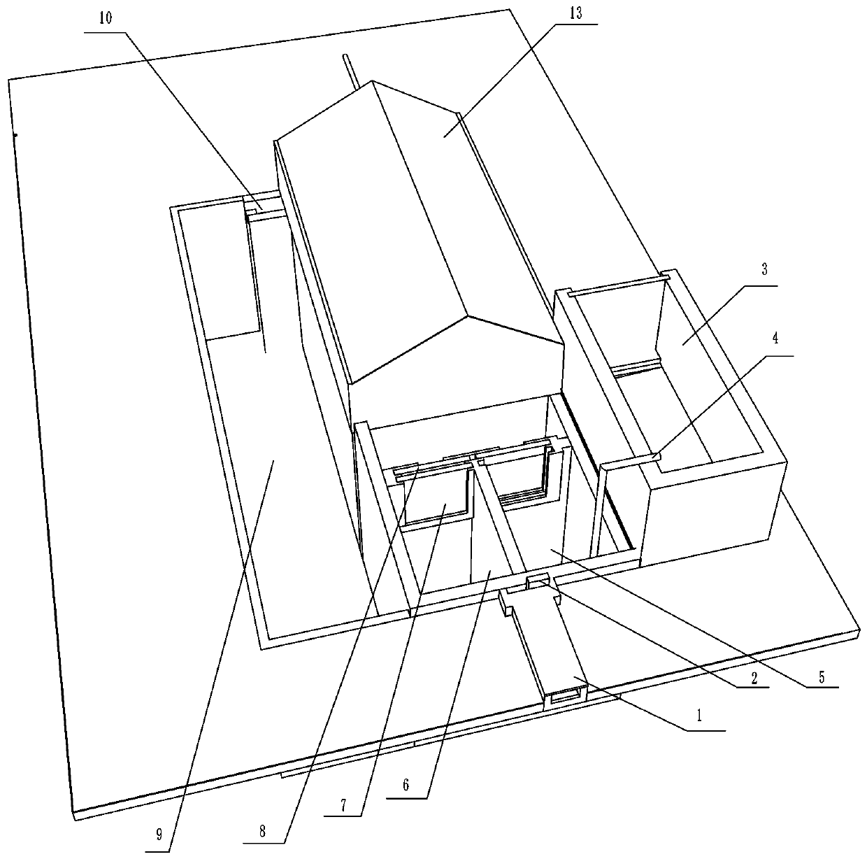
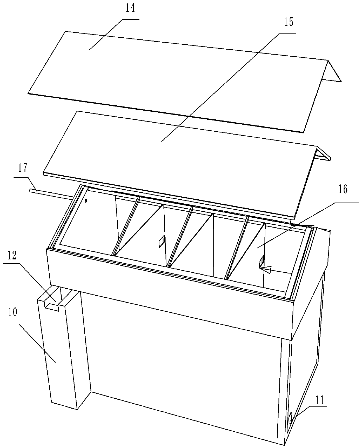
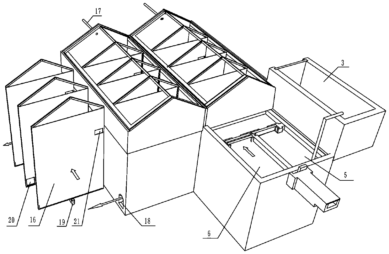
[0034] like figure 1 , figure 2 , image 3 , Figure 4 and Figure 5 As shown, the present embodiment provides an unpowered automatic deflecting type biogas generating device, which includes a solar greenhouse and a biogas generating device arranged inside the solar greenhouse;

[0035] The biogas generating device includes a sewage collection settlement tank, a feed chamber 23, a baffle biogas digester 13, a biogas slurry temporary storage tank 9, and a solid-liquid separation tank 3; the sewage collection settlement tank communicates with the feed chamber 23, and the One side of the bottom of the baffled biogas digester 13 is provided with a feed port 11, the feed port 11 communicates with the feed chamber 23, and the other side of the bottom of the baffled biogas digester is connected with a biogas slurry discharge pipeline 10. The end of the biogas slurry discharge pipe 10 is a biogas slurry discharge upper port 12 . The biogas slurry discharge upper port 12 is flush...


PUM


Abstract

The invention provides an unpowered automatic baffling type biogas generating device. A solar greenhouse and a biogas generating device arranged in the solar greenhouse are included; the biogas generating device includes a sewage collection sedimentation pond, a feeding chamber, a baffling biogas digester, a biogas slurry temporary storage tank and a solid-liquid separation tank; the bottom of thebaffling biogas digester is connected to a biogas slurry discharging pipeline; the top end of the biogas slurry discharging pipeline is flush with the top of the sewage collection sedimentation pond;the baffling biogas digester includes a concrete pool, a black film and a sunlight board, wherein the black film and the sunlight board cover the top of the concrete pool; multiple baffle plates fitting with the two sides of the concrete pool are arranged in the concrete pool; the multiple baffle plates divide the concrete pool into multiple baffling chambers, and water valves are arranged at thebottoms of two adjacent baffling chambers; and the top of the concrete pool is provided with a biogas output pipe. The unpowered automatic baffling type biogas generating device is convenient in maintenance and can make biogas production performance very stable.

Description

technical field [0001] The invention relates to the technical field of sewage treatment, in particular to a non-powered automatic deflecting biogas generating device. Background technique [0002] Farm sewage is a key area of ​​national environmental governance at present and in the future. Biogas technology is the preferred technology for the harmless and resourceful treatment of farm sewage, and other sewage treatment technologies do not have cost advantages. my country has been promoting biogas sewage treatment technology for many years. Farms generally have various types of biogas of different scales. However, more than 80% of biogas projects are in a state of disuse and shutdown. The main reason is that the operating costs are too high and the profits of the farms cannot support ; Daily operation and management are troublesome, maintenance is not in place, and the operation effect is getting worse; it is difficult to discharge materials, easy to crust, and gradually scr...

Claims


Application Information

Patent Timeline
Patent Type & Authority Applications(China)
IPC IPC(8): C12M1/12C12M1/107C12M1/00C02F9/14C02F103/20
CPCC12M21/04C12M23/58C12M23/18C12M33/14C02F9/00C02F3/28C02F1/52C02F1/001C02F2103/20
Inventor 于淑维王聪朱红卫张清锋黄建伟曲连武娄渊志王学君文欣伟梁莎马超
Owner 河南城润环境工程有限公司
Why Eureka
Try Eureka